Appendix A Specifications
A-3
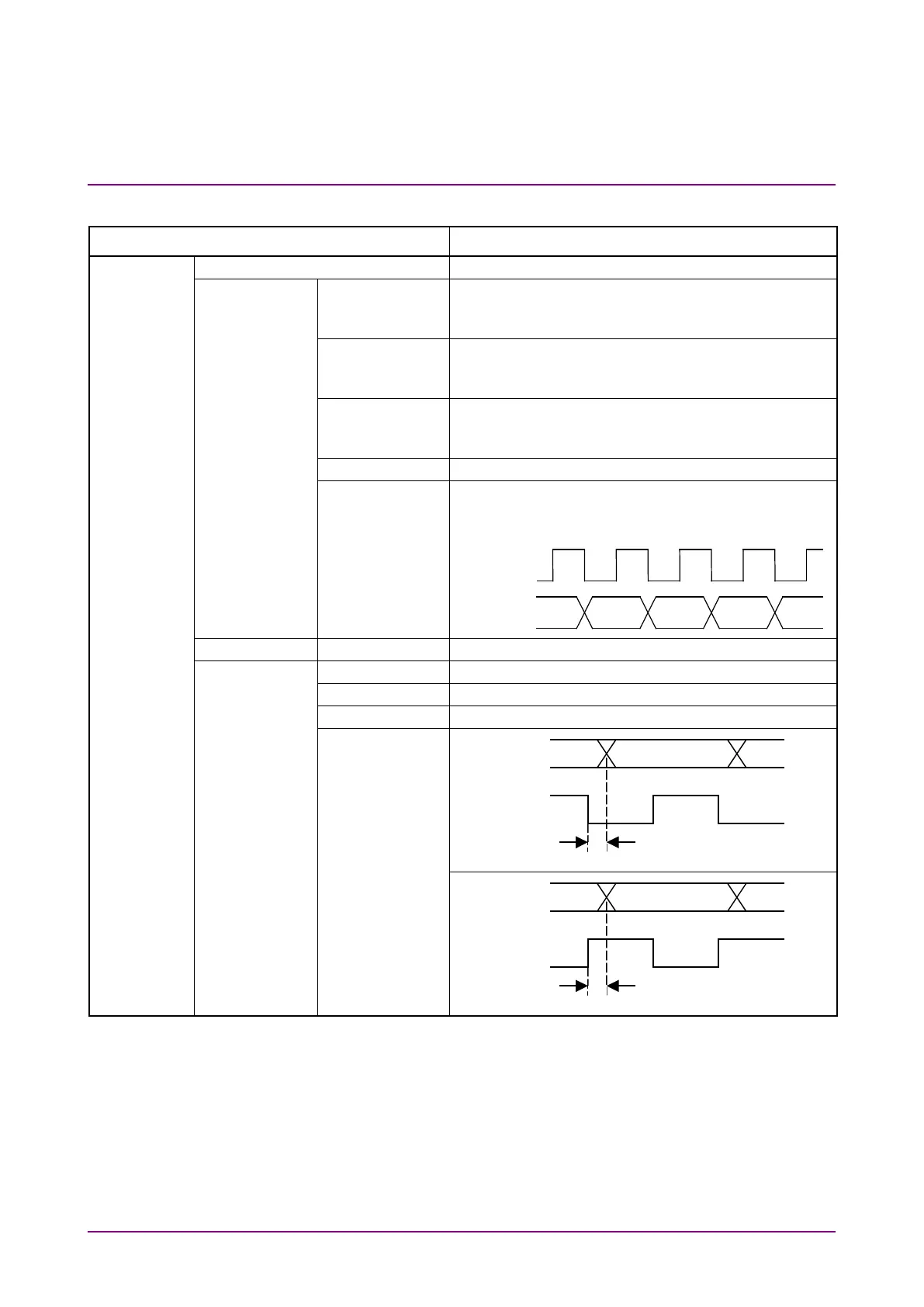
Item Specifications
data/clock en-
able
<ECL> High: 0 to –1.0 V, Low: –1.5 to –2.5 V
<TTL> High: +1.8 to +5.0 V, Low: 0 to +1.0 V
voltage condi-
Variable: –2.5 to +3.3 V (user-defined)
voltage condi-
Variable: –2 to +3 V (user-defined)
Ω
Ω
switching
Clock: Rise, Fall
Enable: Positive, Negative, Off
1 kHz to 155 MHz, Accuracy:
±
100 ppm
±