SECTION 5 – INSTALLATION INSTRUCTIONS
UL EX3470 ULC EX3470
2014-SEP-01 REV. 11 PAGE 5-7
R-102 Restaurant Fire Suppression Manual
AGENT DISTRIBUTION HOSE INSTALLATION
INSTRUCTIONS (Continued)
Restraining Cable Installation (Continued)
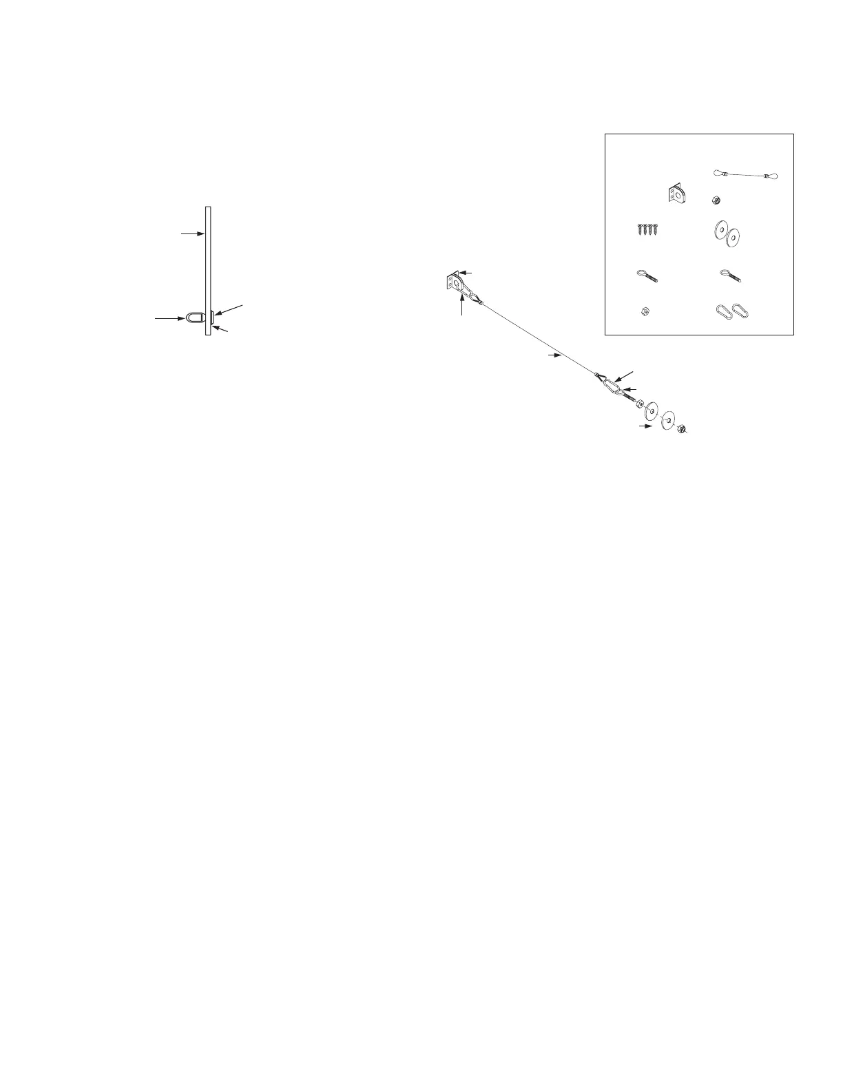
WASHER
BACK OF
APPLIANCE
EYE
NUT
PHILIPS
SCREW
RESTRAINING CABLE – HENNY PENNY-MOUNTED OPTION
FIGURE 5-12
008090
1. The Restraining Cable must be connected from the appli-
ance to the wall or some other structurally sound object
capable of restraining the castered appliance from being
able to be pulled or pushed out to a point that will result in
strain or stress to the Agent Distribution Hose.
2. The Restraining Cable should be installed in line with the
Agent Distribution Hose.
3. For sheet metal covered walls, the Restraining Cable
Assembly includes four 3/4 in. x #8 self tapping sheet
metal screws, and a Restraining Cable Bracket. Securely
attach the Restraining Cable Bracket to the sheet metal
covered wall using the 3/4 in. x #8 self tapping metal screws
provided.
4. For mounting to wall studs, the Restraining Cable Assembly
includes one screw eye lag bolt, 5/16 in. x 2.5 in. (64 mm) long.
5. Locate a structural area (frame) on the rear side of the
equipment that is in line with the wall attachment. Note: It
may be necessary to contact the appliance manufacturer for
a suitable location. Drill a 5/16 in. (7.9 mm) diameter hole.
Use caution when drilling hole, so that internal components
are not damaged.
6. The Restraining Cable Assembly also includes a 5/16 in.
threaded eye-bolt, 5/16 in. hex head nut, 5/16 in nylon lock
nut, and two 5/16 in. flat washers. Thread the included hex
nut onto the eye-bolt. Slide one washer onto the eye-bolt
threads next to the nut. Then, slide the eye-bolt through
the drilled hole and place a washer and nylon locknut onto
the eye-bolt on the inside frame of the equipment. Tighten
securely.
7. Attach one of the snap hooks (included in the Restraining
Cable package) on the end of the Restraining Cable to the
wall bracket and the other snap hook to the eye-bolt (See
Figure 5-13). After snap-hooking the assembly, seal the
Restraining Cable Loops to the wall bracketry and appliance
connection hardware with Lead Wire Seal (Part No. 197).
Note: For the Henny Penny Pressure Fryers that utilize the
ANSUL Henny Penny Fryer Nozzle Kit, Part No. 434455,
the 5/16 in. philips screw supplied in the Henny Penny
Fryer Nozzle Kit, the 5/16 in. eye nut, and 5/16 in. washer
included in the Restraining Cable Assembly Kit, must be
used. (See Figure 5-12).
RESTRAINING CABLE
INSTALLATION PACKAGE
E – 5/16 IN HEX NUT
A – RESTRAINING CABLE
F – 5/16 IN NYLON
LOCK NUT
G – 5/16 IN
X 5/16 IN
WASHERS
(2)
B – STAPLE
BRACKET
C – 3/4 IN. X #8
SCREWS (4)
H – SCREW
EYE BOLT
I – SNAP
HOOK
D – EYE BOLT
B – STAPLE BRACKET
D – EYE BOLT
I – SNAP HOOK
I – SNAP
HOOK
EYE BOLT FASTENING
HARDWARE
A – RESTRAINING
CABLE
FIGURE 5-13
007829
Final Installation Guidelines and Checkout Procedures
After the Agent Distribution Hose and the Restraining Cable is
properly installed, carefully push the appliance back to its normal
operating position. Check that the hose does not have sharp
bends, and is not kinked, twisted, or caught on anything behind
the appliance.
1. Verify the Restraining Cable limits the travel of the appli-
ance and prevents the application of any pull force or
bending stress on the Agent Distribution Hose or hose-to-
pipe connections.
2. Make certain there are no sharp bends and kinks in the
hose when pulling out the cooking equipment.
3. The Agent Distribution Hose should always be in a vertical
natural loop, never having any bends greater than a 3 in.
(76 mm) radius (6 in. (152 mm) diameter), hose twists, or
sharp bends. (See Figure 5-14.) If any of these conditions
exist, the hose and/or hose connections will require installa-
tion modifications.
 Loading...
