SECTION 4 – SYSTEM DESIGN
UL EX3470 ULC EX3470
PAGE 4-52 REV. 11 2014-SEP-01
R-102 Restaurant Fire Suppression Manual
SPECIFIC APPLICATION BY MODEL (Continued)
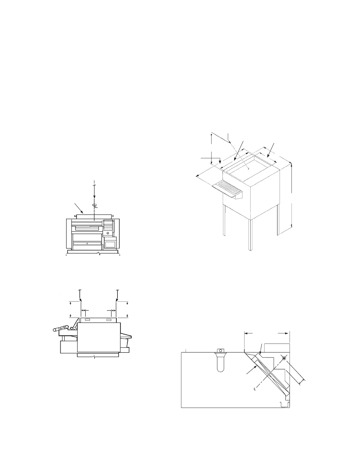
Marshall Air – Model 2001BK Multi-Chamber Broiler
• Nozzle Quantity/Type: Two 1W nozzles
• Nozzle Location: Front nozzle tip must be located 14 in.
(355 mm) directly above the appliance, aligned with the front
face and centerline of the catalytic converter. The aim point is
4 in. (101 mm) forward of the front edge of the converter on
the centerline.
The rear nozzle tip is a mirror image of the front. The rear
nozzle is located 14 in. (355 mm) vertically above the appli-
ance, aligned with the “rear” face and centerline of the cata-
lytic converter. The aim point is 4 in. (101 mm) behind the
“rear” edge of the converter on the centerline. See Figure
4-102.
• System Limitation: Maximum of ve ows for a 3.0 gallon
system: Remaining ow points available may be used to
protect other hazards.
TWO 1W NOZZLES
003418a
CONVERTER
FRONT VIEW
CENTERED ON CONVERTER
NOZZLE ALIGNED WITH
FRONT OF CONVERTER,
AIMED 4 IN. (101 mm) BACK
NOZZLE ALIGNED WITH BACK
OF CONVERTER, AIMED
4 IN. (101 mm) FORWARD
1W
NOZZLE
1W
NOZZLE
4 IN.
(101 mm)
003418B
SIDE VIEW
NOZZLE ALIGNED WITH FRONT OF CONVERTER
14 IN.
(355 mm)
14 IN.
(355 mm)
FIGURE 4-102
Marshall Air Electric Broiler – Model FR14B AutoBroil
Nozzle Quantity/Type: One 260 Nozzle
Nozzle Height:
15 – 20 in. (381 – 508 mm) above the
top of the broiler
Nozzle Location:
The nozzle must be centered above the
front edge of the broiler
Nozzle Aiming Point:
Aimed at the center of the exhaust
opening of the broiler. See Figure
4-103.
FIGURE 4-103
006737
Grease Grabber-80™ Two Stage Filtration System
The Grease Grabber-80 Two Stage Filtration System consists of
two components: The primary lter (The Grease-X Tractor) and
the secondary lter (The Grease Grabber-80).
The protection required for this application is the same as the
standard plenum/lter protection: One 1N nozzle protecting 10
(3.0 m) linear feet of plenum length by 4 ft (1.2 m) of plenum
chamber depth (width), positioned 2 in. to 4 in. (51 mm to 102 mm)
from peak of secondary lter. See Figure 4-104.
FIGURE 4-104
006526
15 – 20 IN.
(381 – 508 mm)
24.25 IN.
(615 mm)
24 IN.
(609 mm)
48 IN.
(1219 mm)
34.69 IN.
(881 mm)
14.50 IN.
(368 mm)
SECONDARY
FILTER
NOTE: TWO NOZZLES MUST BE UTILIZED FOR V-BANK FILTER
ARRANGEMENT.
PRIMARY
FILTER
1N
NOZZLE
2-4 IN.
(51-102 mm)
4 FT. (1.2 m)
MAXIMUM

 Loading...