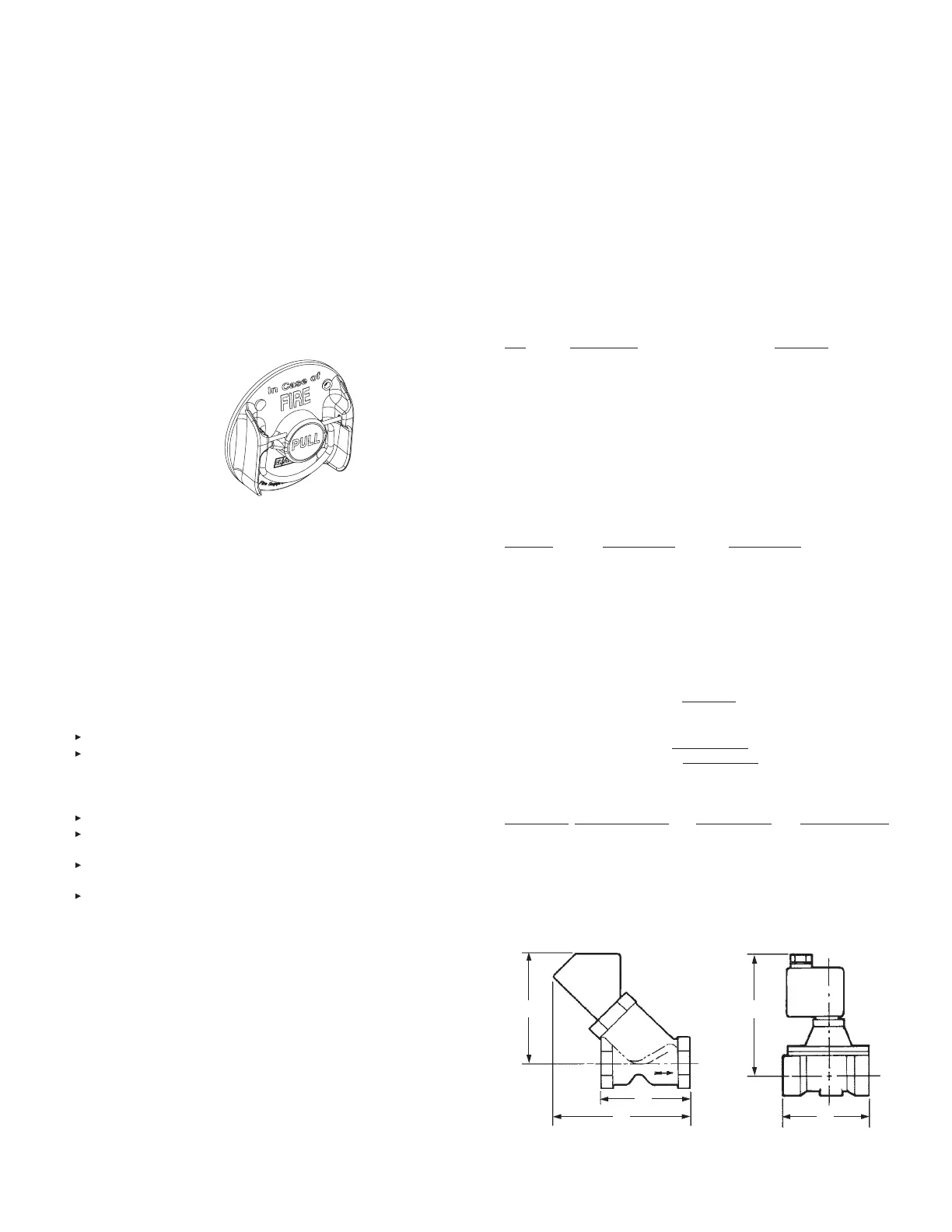
REMOTE MANUAL PULL STATION
The remote manual pull station (Part No. 434618 or 435960)
is made out of a molded red composite material. The red color
makes the pull station more readily identifiable as the manual
means for fire suppression system operation. The pull station
is compatible with the ANSUL Flexible Conduit. The molded
manual pull station should be mounted at a point of egress
and positioned at a height determined by the authority having
jurisdiction. Trim Rings (Part No. 427074) (pack of 10), are
available.
Part No. 434618 (Without Wire Rope)
Part No. 435960 (With 50 ft (15.2 m) of Wire Rope)
FIGURE 3-26
008326
FLEXIBLE CONDUIT
Flexible conduit allows for quicker installations and the conve-
nience of being able to route the cable over, under and around
obstacles. Flexible conduit can be used as a substitute for stan-
dard EMT conduit or can be used with EMT conduit. Flexible
conduit can be used only with the Molded Manual Pull Station
(Part No. 434618) and mechanical gas valve installations. The
Flexible Conduit comes in a 500 ft (152.4 m) length (Part No.
434525) or together with 500 ft (152.4 m) of wire rope (Part No.
435959).
A 50 ft (15.2 m) Flexible Conduit pre-fed with wire rope (Part
No. 439104) is available.
Also available is a Flexible Conduit Strain Relief (50-pack) (Part
No. 435979).
A 50-pack of Flexible Conduit Inserts (Part No. 434347) and a
50-pack of P-Clips (Part No. 436150) are also available.
Note 1: Flexible conduit is intended for indoor use ONLY.
Note 2: Flexible conduit cannot be used in detection sys-
tems.
MECHANICAL GAS VALVES
The mechanical gas valves are designed to shut off the flow of
gas to the appliances upon actuation of the regulated release
assembly. The valves are available in sizes of 3/4 in., 1 in., 1
1/4 in., 1 1/2 in., and 2 in. ANSUL style; and 2 1/2 in. and 3 in.
ASCO style. The valves are rated for natural and LP gas. Both
styles are UL Listed and includes the air cylinder, tubing, and
fittings (Part No. 15733) for connection to the release mecha-
nism.
Maximum
Part Operating
No. Description Pressure
55598 3/4 in. Gas Valve (ANSUL) 10 psi (0.69 bar)
55601 1 in. Gas Valve (ANSUL) 10 psi (0.69 bar)
55604 1 1/4 in. Gas Valve (ANSUL) 10 psi (0.69 bar)
55607 1 1/2 in. Gas Valve (ANSUL) 10 psi (0.69 bar)
55610 2 in. Gas Valve (ANSUL) 10 psi (0.69 bar)
25937 2 1/2 in. Gas Valve (ASCO) 5 psi (0.35 bar)
25938 3 in. Gas Valve (ASCO) 5 psi (0.35 bar)
Flow Capacity BTU/HR, at 1 in. P.D.
(CFH) 0.64 SP GR
Pipe Size P.D. 1 in. WC 1000 BTU/ft
3
(inches) 0.64 SP GR Natural Gas
3/4 751 751,000
1 1288 1,288,000
1 1/4 1718 1,718,000
1 1/2 2630 2,630,000
2 4616 4,616,000
2 1/2 5700 5,800,000
3 7100 7,300,000
To calculate gas flow for other than 1 inch p.d.:
New cfh = (cfh at 1 inch) x u new p.d.
To calculate gas flow for other than 0.64 SP GR:
New cfh = (cfh at 0.64) x u 0.64
New SP GR
A B C
Valve Size in. (mm) in. (mm) in. (mm)
3/4 in. 3 3/4 (95.3) 6 3/8 (161.9) 5 1/2 (139.7)
1 in. 3 3/4 (95.3) 6 3/8 (161.9) 5 1/2 (139.7)
1 1/4 in. 4 7/8 (123.8) 7 3/8 (187.3) 6 3/8 (161.9)
1 1/2 in. 4 7/8 (123.8) 7 3/8 (187.3) 6 3/8 (161.9)
2 in. 5 7/8 (149.2) 7 7/8 (200.0) 6 11/16 (169.9)
2 1/2 in. 7 13/16 (198.4) ----- 9 1/16 (230.2)
3 in. 7 25/32 (197.6) ----- 9 1/16 (230.2)
FIGURE 3-27
SECTION 3 – SYSTEM COMPONENTS
UL EX3470 ULC EX3470
2014-SEP-01 REV. 11 PAGE 3-9
R-102 Restaurant Fire Suppression Manual
A
B
C
004208
3/4 IN. THRU 2 IN.
A
004209
2 1/2 IN. THRU 3 IN.
C

 Loading...