SECTION 5 – INSTALLATION INSTRUCTIONS
UL EX3470 ULC EX3470
PAGE 5-18 REV. 11 2014-SEP-01
R-102 Restaurant Fire Suppression Manual
INSTALLING REMOTE MANUAL PULL
STATION (Continued)
INSTALLATION FOR REMOTE MANUAL PULL STATION
UTILIZING EMT CONDUIT ONLY (Continued)
RELEASE
MECHANISM
OVAL
SLEEVE
CABLE
LEVER
OPTIONAL:
PULLEY TEE CAN
BE LOCATED IN
THIS POSITION
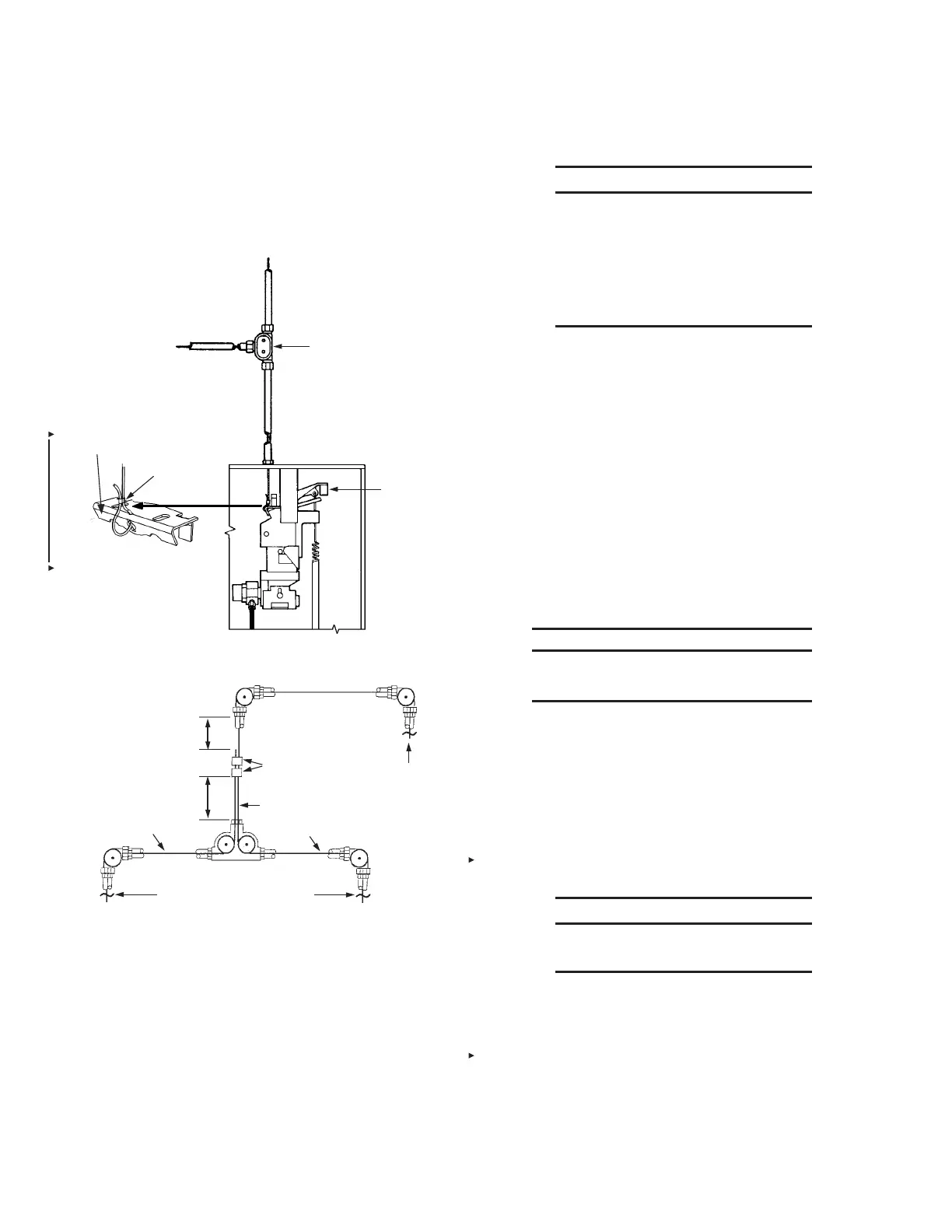
REMOTE MANUAL PULL STATION APPLICATION – OPTION 3
FIGURE 5-40
009466
TO AIR
CYLINDER
FOR GAS
VALVES OR
RELEASE
CABLE
LEVER
FOR PULL
STATIONS
NO ELBOWS ALLOWED
WHERE TWO WIRE
ROPES ARE PRESENT
2 - OVAL SLEEVES
(PART NO. 4596)
PULLEY TEE (PART
NO. 427929) ONLY
TO EITHER GAS VALVES OR PULL
STATIONS. MIXING IS NOT ALLOWED.
TWO WIRE ROPES CONNECTED BETWEEN A PULLEY
ELBOW AND A PULLEY TEE
SPLICED WIRE
ROPE
CONTINUOUS WIRE
ROPE
MINIMUM OF
6 IN. (153 mm)
MINIMUM OF
6 IN. (153 mm)
FIGURE 5-41
008393
4. Feed wire rope from the AUTOMAN release through conduit
and pulley elbows and pulley tee, if provided, to the pull
station junction box. Follow the instructions for assembling
the pull station and block assembly and attaching the wire
rope to the pull station pull knob (see Figures 5-70 through
5-85).
NOTICE
Make certain that wire rope rides on top
and in center of pulley sheave. If the 50
ft (15.2 m) wire rope has been spliced
to accommodate a longer run, do not
allow the spliced ends to be within 6 in.
(153 mm) of any pulley elbow or conduit
adaptor.
5. Fasten pull station assembly to each junction box (if junction
box is used).
6. Slide oval crimp sleeve onto wire rope. Loop wire rope
through cable lever guide holes and back through the oval
crimp sleeve. See Figure 5-37.
7. Pull slack out of each wire rope and crimp sleeve. (Use the
National Telephone Supply Company Nicopress Sleeve
Tool Stock No. 51-C-887 or equal to properly crimp stop
sleeve.) See Figure 5-37.
Note: When utilizing flexible conduit for remote manual pull
station or mechanical gas valve installation, refer to “Installation
of Remote Manual Pull Station or Mechanical Gas Valve Utilizing
Flexible Conduit” instructions on pages 5-22 through 5-34.
INSTALLING MECHANICAL GAS VALVE
NOTICE
Mechanical gas valves are designed for
indoor installation only.
To install each Mechanical Gas Shut-off Valve complete the
following steps. (All gas valve installation and testing shall be
made in accordance with the authority having jurisdiction.)
Note: Mechanical gas valve air cylinder(s) can be installed
in regulated release assemblies and also regulated actuator
assemblies. Installation in either is the same.
1. Make certain that regulated release assembly enclosure
cover is detached and lock pin is properly inserted in the
regulated release mechanism.
NOTICE
Failure to follow these instructions may
lead to system actuation.
2. Verify that cartridge has been removed from regulated
release assembly and that the regulated release mecha-
nism is in the cocked position.
If regulated release mechanism does not have lock pin
inserted or cartridge removed, refer to the “Semi-Annual
Main ten ance,” Page 8-1, in “Maintenance Examination”
section, and complete Steps 2 and 3 before completing the
following installation steps.
 Loading...
