SECTION 4 – SYSTEM DESIGN
UL EX3470 ULC EX3470
2014-SEP-01 REV. 11 PAGE 4-61
R-102 Restaurant Fire Suppression Manual
TANK AND CARTRIDGE REQUIREMENTS
Once the hazard analysis is completed and the total nozzle ow
numbers are established, the quantity and size of agent tanks
and cartridges needed to supply the nozzles with the proper
volumes of agent at the proper ow rates can be determined.
For cartridges used in the regulated release mechanism, ow
capacities, tank quantities and sizes, and regulated release
cartridge options are given in the table below.
Total Quantity and Regulated Release
Flow Size of Cartridge Options
Numbers* Tank(s) Nitrogen Carbon Dioxide
1 – 5 (1) 1.5 Gallon LT-20-R 101-10
6 – 11 (1) 3.0 Gallon LT-30-R 101-20
11 – 16 (1) 1.5 Gallon Double 101-30
(1) 3.0 Gallon
16 – 22 (2) 3.0 Gallon Double 101-30**
16 – 22 (2) 3.0 Gallon Double –
(Manifold)
22 – 33 (3) 3.0 Gallon Double –
When one or more regulated actuators are used, the following
tank and cartridge combinations apply for each regulated actu-
ator:
Regulated Actuator Regulated Actuator
Tank(s) Cartridge
(1) 1.5 Gallon LT-20-R or 101-10
(1) 3.0 Gallon LT-30-R or 101-20
(1) 1.5 Gallon and LT-A-101-30 or 101-30** or
(1) 3.0 Gallon double tank
(2) 3.0 Gallon LT-A-101-30 or 101-30** or
double tank
(2) 3.0 Gallon (Manifold) LT-A-101-30 or Double
(3) 3.0 Gallon LT-A-101-30 or Double
* For exceptions to maximum ow numbers, see Distribution Piping Requirements for 1.5
gallon and 3.0 gallon systems in this Section.
** The 101-30 cartridge can not be used when two 3.0 gallon tanks are manifolded together.
For higher total ow numbers (23 to 110), multiple cartridges
and regulated actuators are required as shown in the System
Selection Guide in “Appendix” Section
ACTUATION AND EXPELLANT GAS LINE REQUIREMENTS
This section contains the guidelines for installing the actuation
and expellant gas lines between the regulated release mech-
anism regulator, each regulated actuator regulator, and each
agent tank. These limitations should be considered when select-
ing the component mounting locations.
The actuation gas line is the length of pipe and/or hose that is
run from either the AUTOMAN Regulated Release Assembly or
the Remote Release Assembly that directs high pressure from
the cartridge in the release to actuate one or more additional
Regulated Actuator Assemblies. The actuation gas line can
consist of 1/4 in. Schedule 40 black iron, chrome-plated, stain-
less steel, or galvanized steel pipe and ttings, and/or factory
supplied stainless steel braided actuation hose.
The expellant gas line is the length of pipe that is run from the
regulator in either the AUTOMAN Regulated Release Assembly
or a Regulated Actuator Assembly that directs regulated pres-
sure to the agent storage tanks to pressurize the tank and
discharge the agent. The expellant gas line shall consist of 1/4
in. Schedule 40 black iron, chrome-plated, stainless steel, or
galvanized steel pipe and ttings.
Actuation Gas Line – 6 to 8* Tanks Maximum
* 8 Tank maximum reflects the utilization of 3 tank regulated actuators.
1. Use only 1/4 in. Schedule 40 black iron, hot-dipped galva-
nized, chrome-plated, or stainless steel pipe and ttings.
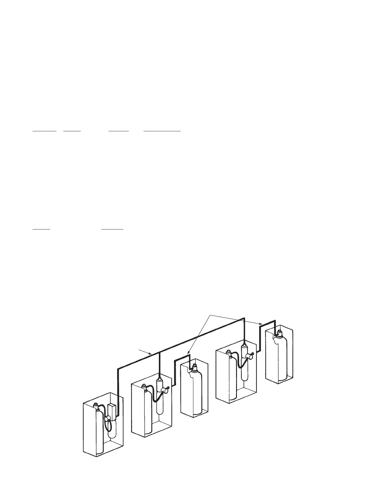
2. The actuation gas line piping is installed from the regulated
release mechanism to each regulated actuator connected
within the system. The total length of the actuation gas line
from the regulated release assembly to the regulated actua-
tor assembly(ies) must not exceed 20 ft (6.0 m) when using
an LT-20-R, an LT-30-R nitrogen cartridge, or a 101-10 or a
101-20 carbon dioxide cartridge. See Figure 4-121.
FIGURE 4-121
000775
ACTUATION GAS LINE WITH AN LT-20-R,
LT-30-R, 101-10 OR 101-20 CARTRIDGE
MAXIMUM LENGTH OF 20 FT (6.0 m);
MAXIMUM NO. OF FITTINGS 9
REGULATED ACTUATOR ASSEMBLY
EXPELLANT GAS LINES
NOT INCLUDED IN ACTUATION
GAS LINE LENGTH TOTALS
REGULATED
ACTUATOR
ASSEMBLY
AUTOMAN
REGULATED RELEASE
ASSEMBLY
REGULATED
ACTUATOR
ASSEMBLY

 Loading...