SECTION 5 – INSTALLATION INSTRUCTIONS
UL EX3470 ULC EX3470
PAGE 5-24 REV. 11 2014-SEP-01
R-102 Restaurant Fire Suppression Manual
INSTALLATION OF REMOTE MANUAL PULL STATION OR
MECHANICAL GAS VALVE UTILIZING FLEXIBLE CONDUIT
(Continued)
Connecting the Flexible Conduit to the AUTOMAN
Release, Electrical Junction Box, or Mechanical Gas Valve
(Continued)
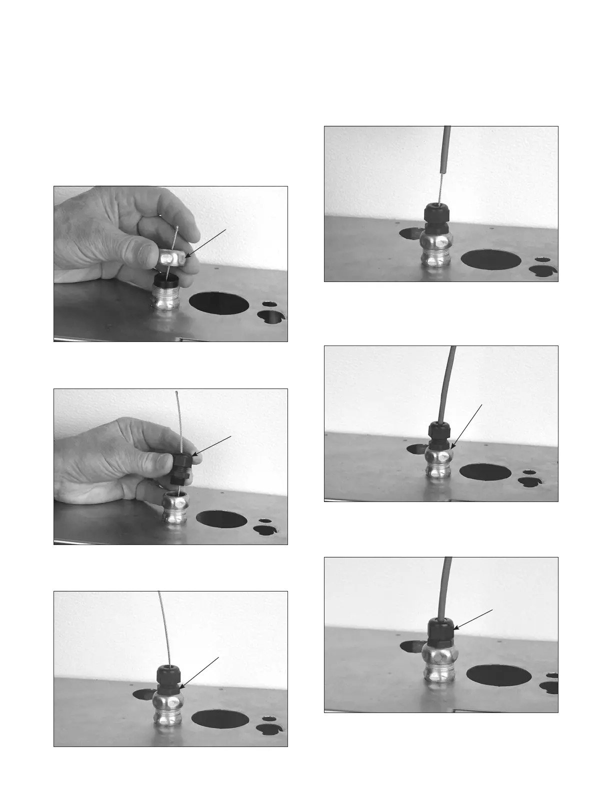
5. Tighten the nut to the connector body, locking the flexible
conduit insert in place. See Figure 5-56.
TIGHTEN
CONNECTOR
NUT TO LOCK
IN FLEXIBLE
CONDUIT
INSERT
FIGURE 5-56
007989
6. Loosen the nut on the strain relief and thread the wire rope
through a strain relief. See Figure 5-57.
LOOSEN
NUT
FIGURE 5-57
007990
7. Tighten the body of the strain relief to the conduit connector.
See Figure 5-58.
TIGHTEN
STRAIN RELIEF
INTO CONDUIT
CONNECTOR
FIGURE 5-58
007991
8. Thread the wire rope through the flexible conduit. See
Figure 5-59. (If a splice is required in the flexible conduit,
proceed to “Splicing Installation Instructions.”
FIGURE 5-59
007992
9. Slide the flexible conduit into the strain relief until it is
approximately 1/16 in. (1.6 mm) from the bottom of the flex-
ible conduit insert. See Figure 5-60.
STOP FLEXIBLE
CONDUIT
APPROXIMATELY
1/16 IN. (1.6 mm)
FROM THE BOTTOM
OF INTERNAL
FLEXIBLE CONDUIT
INSERT
FIGURE 5-60
007993
10. Tighten the strain relief nut onto the strain relief. See Figure
5-61.
TIGHTEN NUT
ON STRAIN
RELIEF
FIGURE 5-61
007994
 Loading...
