SECTION 6 – TESTING AND PLACING IN SERVICE
UL EX3470 ULC EX3470
PAGE 6-2 REV. 11 2014-SEP-01
R-102 Restaurant Fire Suppression Manual
TESTING MECHANICAL GAS VALVES (Continued)
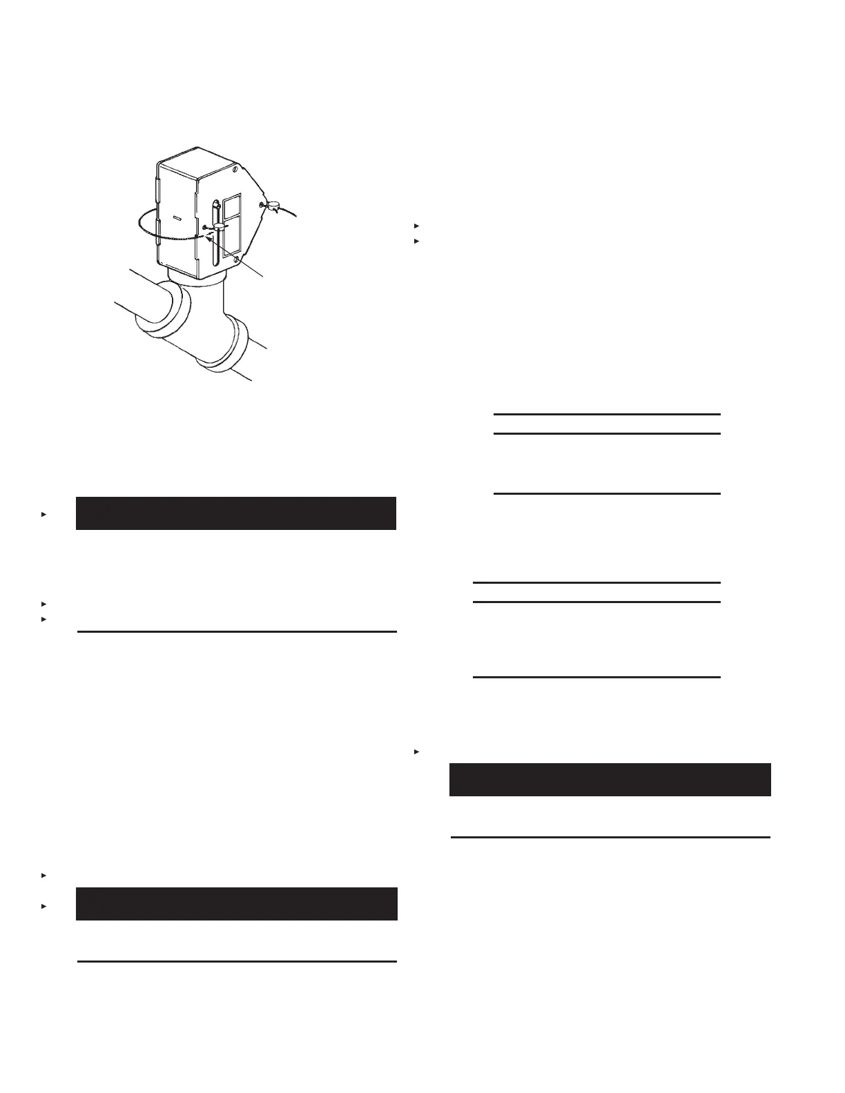
VISUAL INSPECTION
SEAL (PART NO. 197)
FIGURE 6-1
000359
TESTING ELECTRICAL GAS VALVES
To test each Electric Gas Shut-off Valve complete the following
steps:
1.
!
WARNING
To reduce the risk of explosion due to leaking gas, before
the gas line is turned on, make certain to extinguish any
open flames and turn off all burners and any electrical
or mechanical devices that are capable of igniting gas.
Failure to comply may result in serious personal injury or
death.
Turn gas line on.
2. Make certain electric (snap-action) switch is properly wired.
3. Make certain all other devices connected to the manual
reset relay are properly wired. Refer to typical wiring
diagrams in Figures 5-122, 5-123, 5-124, and 5-125 in
“Installation Instructions” section.
4. Test for gas leaks by painting connections with a soap
solution. Bubbles indicate a gas leak. Tighten connections
where leaks appear. Repeat test again to make certain no
other gas leaks exist.
5. If no gas leaks are found, turn power source on and depress
theresetbuttononthemanualresetrelay(REDLIGHTON)
to energize (OPEN) electric gas valve.
6. Remove lock pin from regulated release mechanism.
CAUTION
Do not install cartridge at this time or system may be
actuated.
7. Manually actuate the system by operating the remote pull
station. (It may be necessary to remove the glass break
rodpriortooperatingpullstation.)Manualresetrelay(RED
LIGHT OUT) will de-energize (CLOSE) the electric gas
valve, thus shutting off the gas line. If this does not happen,
turn power source off. Then re-examine all wiring connec-
tions for proper hookup. Refer to Figures 5-122, 5-123,
5-124, and 5-125 in ‘‘Installation Instructions’’ section for
typical wiring diagrams.
8. If test is successful, recock regulated release mechanism
using cocking lever (Part No. 441042 or 441041) and rein-
stall lock pin (Part No. 438301). Depress reset button on
manualresetrelay(REDLIGHTON).
9. Check burners for gaseous odor. IF GASEOUS ODOR
EXISTS, TURN OFF POWER SOURCE IMMEDIATELY.
This will cause the electric gas valve to shut the gas line off.
Open any doors and/or windows to clear the area of
gaseous fumes, then correct the gas leak before proceeding
any further.
10. If no gaseous odor exists, pilot light may be ignited at this
time.
NOTICE
If no other devices are being attached,
proceed to Page 6-3, Step No. 1, and test
the detection system.
TESTING ELECTRIC SWITCH
The procedure for testing a field installed electric (snap-action)
switch is as follows:
NOTICE
If an electrical gas shut-off valve is attached
to system, perform proper test procedure
for the gas valve first, before completing the
following steps.
1. Turn power source on and if installed, depress reset button
on manual reset relay (RED LIGHT ON). All electrical
devices should be operating at this time.
2. Remove lock pin.
CAUTION
Do not install cartridge at this time or system may be
actuated.
3. Manually actuate the system by operating the remote pull
station. It may be necessary to remove the glass break rod
prior to operating pull station. (If installed, the manual reset
relay will de-energize the electric gas valve, thus shutting
off the gas line.) All electrically-operated devices prede-
termined to shut off or turn on should do so. If this does
not occur, turn power source off and make sure all wiring
is properly connected and retest. Refer to Figures 5-122,
5-123, 5-124, and 5-125 in “Installation Instructions” section
for typical wiring diagrams.
 Loading...
