Duct Protection – Multiple Nozzle
DUCT SIZES UP TO 135 IN. (3429 mm) PERIMETER –
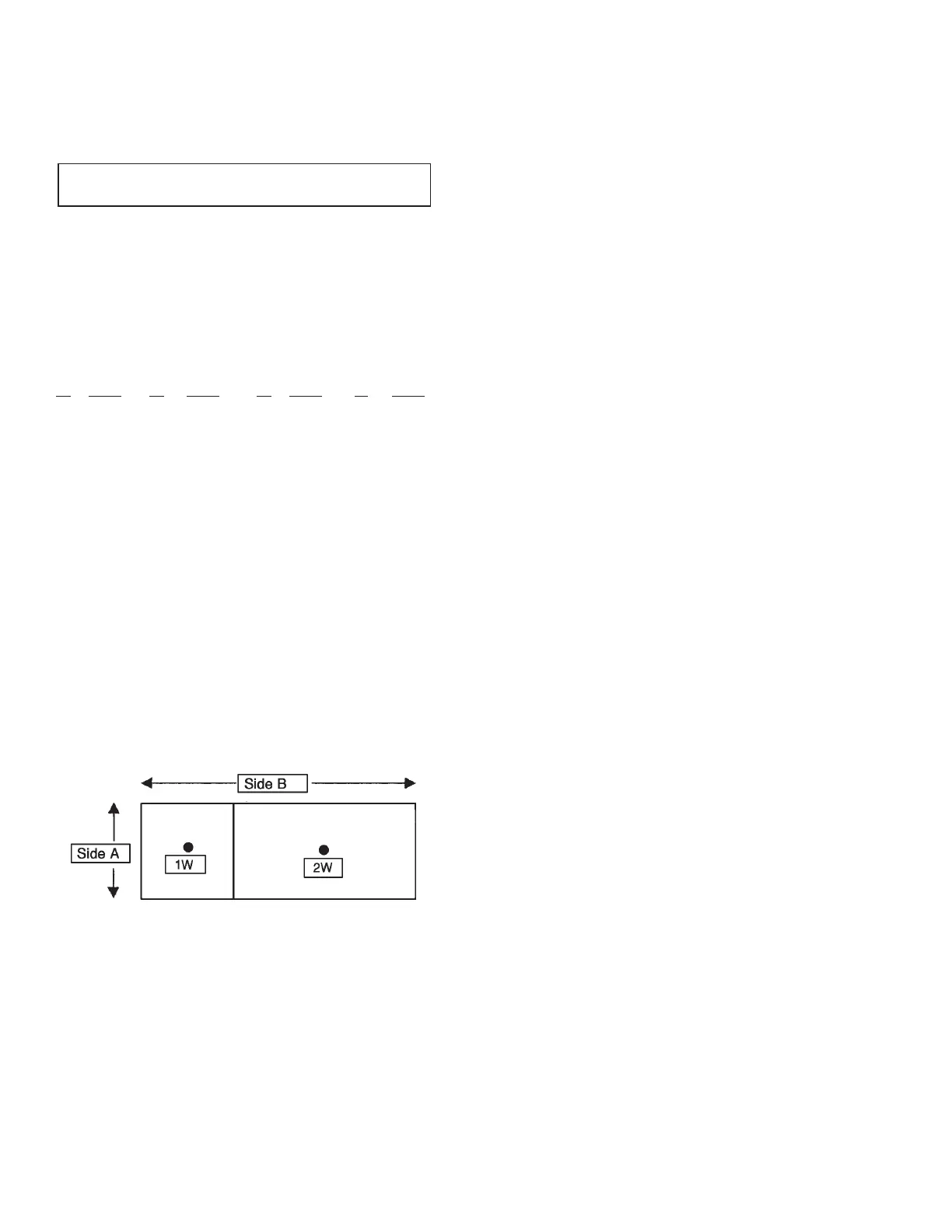
THREE FLOW OPTION
• One 1W nozzle and one 2W nozzle = three ow numbers
• 135 in. (3429 mm) perimeter maximum
• No round duct option available
• Follow design table in Figure 4-2 to determine maximum
module size for each nozzle
1W Module 2W Module
Side A Side B Side B Side B
Maximum Maximum Maximum Maximum
in. (mm) in. (mm) in. (mm) w. (mm)
4 (101) 60.0 (1524) 23.0 (584) 37.0 (939)
5 (127) 60.0 (1524) 23.0 (584) 37.0 (939)
6 (151) 59.5 (1511) 22.5 (571) 37.0 (939)
7 (177) 59.0 (1498) 22.0 (558) 37.0 (939)
8 (203) 58.5 (1485) 22.0 (558) 36.5 (927)
9 (228) 58.0 (1473) 21.5 (546) 36.5 (927)
10 (254) 57.0 (1447) 21.0 (533) 36.0 (914)
11 (279) 56.0 (1422) 20.5 (520) 35.5 (901)
12 (304) 55.5 (1409) 20.0 (508) 35.5 (901)
13 (330) 54.5 (1384) 19.5 (495) 35.0 (889)
14 (355) 53.5 (1358) 18.5 (469) 35.0 (889)
15 (381) 52.0 (1320) 18.0 (457) 34.0 (863)
16 (406) 51.0 (1295) 17.0 (431) 34.0 (863)
17 (431) 49.5 (1257) 16.0 (406) 33.5 (850)
18 (457) 47.5 (1206) 14.5 (368) 33.0 (838)
19 (482) 46.0 (1168) 13.5 (342) 32.5 (825)
20 (508) 43.5 (1104) 12.0 (304) 31.7 (805)
21 (533) 41.0 (1041) 10.0 (254) 31.0 (787)
22 (558) 38.0 (965) 7.5 (190) 30.5 (774)
23 (584) 33.5 (850) 4.0 (101) 29.5 (749)
FIGURE 4-2
006521
Example: Protection is required for a duct that has an “A”
dimension of 8 in. (203 mm) wide and a “B” dimension of 55 in.
(1397 mm) long.
Referring to the table in Figure 2, if the “A” dimension is
8 in. (203 mm), the “B” dimension must not exceed 58.5
in. (1485 mm). In this example, the “B” dimension is 55 in.
(1397 mm), therefore, this duct can be protected with a three
ow application.
Read over from the 8.0 in. (203 mm) line on the table to the
1W Module column. At that point, the chart shows that the “B”
module length for the 1W nozzle can be 22.0 in. (558 mm).
Center the 1W nozzle in that module. The 2W module can now
be centered within the remaining module.
SECTION 4 – SYSTEM DESIGN
UL EX3470 ULC EX3470
PAGE 4-2 REV. 11 2014-SEP-01
R-102 Restaurant Fire Suppression Manual
 Loading...
