SECTION 4 – SYSTEM DESIGN
UL EX3470 ULC EX3470
2014-SEP-01 REV. 11 PAGE 4-71
R-102 Restaurant Fire Suppression Manual
DETECTION SYSTEM REQUIREMENTS
Once the re suppression system design has been determined,
a detection system design must be completed. This section
contains guidelines and limitations for detection system instal-
lation.
Detector Identification
The two types of detectors are distinguished from each other by
their location in the detection system.
1. The Terminal Detector is the last in a series of detectors,
or the only detector used in a single-detector system. This
detector is thus named because it is at the point at which the
wire rope ends, or “terminates.”
2. A Series Detector is any detector located in-line between the
regulated release mechanism and the terminal detector.
Detector/Pulley Elbow/Conduit Offset Design Limitations
1. Conduit runs, pulley elbows, and number of detectors per
system must be within the approved system guidelines. The
following requirements must not be exceeded:
Maximum Maximum Maximum
Number of Number of Length of
Detectors Elbows 1/2 in. Conduit
per System per System per System
Scissors Style 15 20 150 ft (45.7 m)
Detector
(Without
Offset Conduit
Scissors Style 15 16 150 ft (45.7 m)
Detector (With
Offset Conduit
2. If the hazard requires more than 15 detectors, up to ve
101 Remote Releases (Part No. 433485) can be used for
system actuation. Each 101 remote release allows the use
of a maximum of 15 “scissor” style detectors (14 series and
1 terminal) for a total of 75 detectors if needed.
Detector Placement Requirements
EXHAUST DUCTS
Each exhaust duct must have at least one detector installed
in the duct entrance, located in the airstream of the cooking
vapors, or at a maximum of 20 ft (6.0 m) into the duct opening.
See Figure 4-139
FIGURE 4-139
000271
NOTICE
When gas appliances are used and the flue
gases from the burner are exhausted into the
duct, the detector must be kept out of the air
stream of these exhaust gases. These gases
can be very hot and could actuate the system
unnecessarily.
Duct openings that are long and narrow or
large enough to require multiple duct nozzles
may require additional detectors.
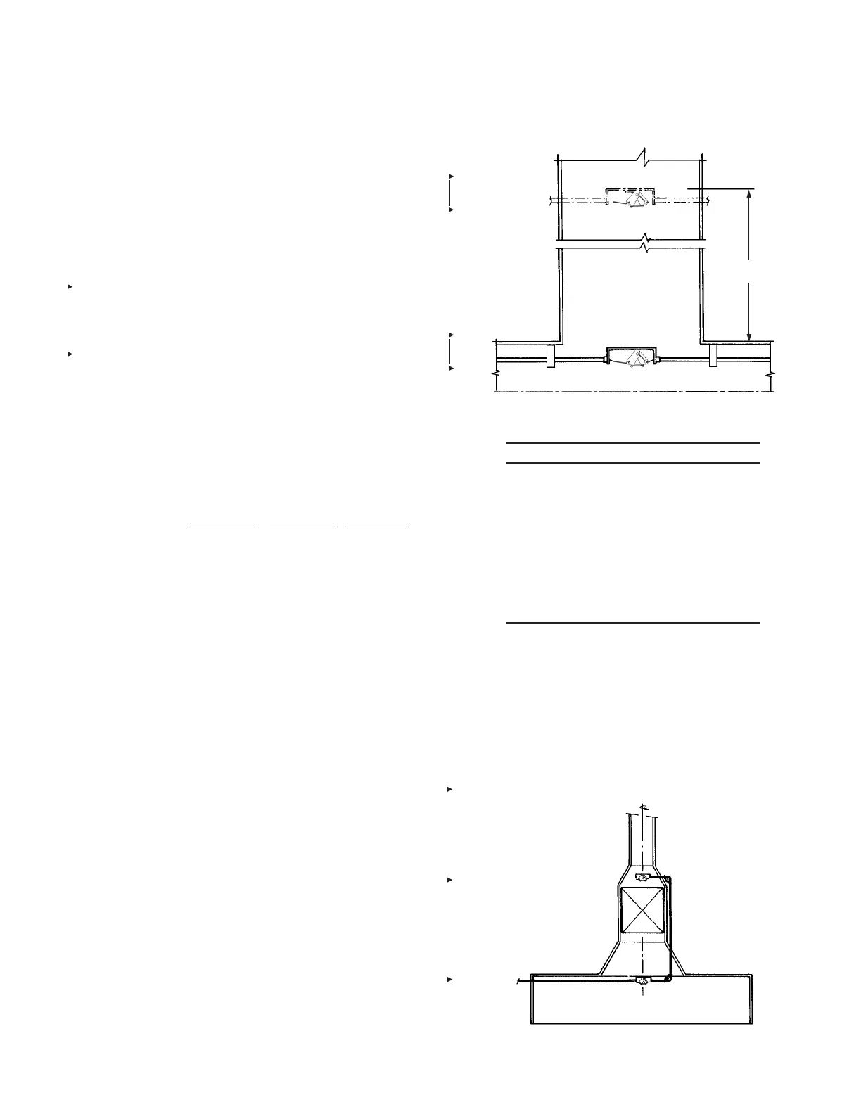
ELECTROSTATIC PRECIPITATOR
If an electrostatic precipitator is located at or near the base of
the exhaust duct, it is necessary to locate a detector below the
precipitator, at the base of the duct, and also locate one in the
duct, just above the precipitator. See Figure 4-140.
When installing the detector bracket and system conduit, make
certain they do not interfere with the operation of the precipitator.
Note:
On secondary ltration units utilizing multiple lter stages/
media, contact Technical Services for instructions.
FIGURE 4-140
000268
20 FT (6.0 m)
MAXIMUM

 Loading...