SECTION 4 – SYSTEM DESIGN
UL EX3470 ULC EX3470
PAGE 4-70 REV. 11 2014-SEP-01
R-102 Restaurant Fire Suppression Manual
DISTRIBUTION PIPING REQUIREMENTS (Continued)
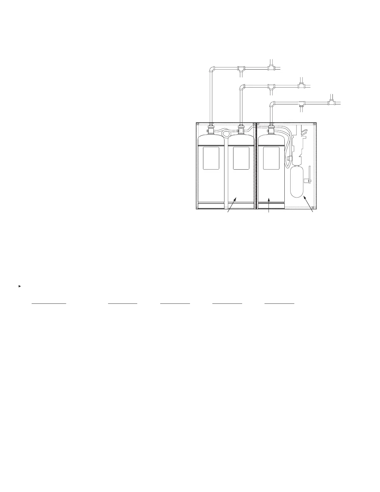
Distribution Piping Requirements – 9.0 Gallon System
This optional conguration consists only of three 3-gallon tanks,
all pressurized from a single double-tank nitrogen cartridge with
expellant gas hoses connected as shown in Figure 4-138. Tanks
No. 1 and No. 2 must be connected directly to the regulator with
separate expellant gas hoses and Tank No. 3 must be connected
to Tank No. 2 with a third expellant gas hose as shown in Figure
4-136. Each tank must be connected to an independent distribu-
tion piping network as shown in Figure 4-138. Distribution piping
requirements for each network must be as follows:
1. The maximum length between the start of the rst branch
line and the start of the last branch line must not exceed
24 ft (7.3 m). When the supply line is split, the combined
total of both legs of the supply line (from the start of the
rst branch line to the start of the last branch line) must not
exceed 24 ft (7.3 m). See Figure 4-134.
2. The total length of all branch lines must not exceed 36 ft
(10.9 m). See Figure 4-138.
3. Use a 3/8 in. union to connect the tank adaptor to the 3/8 in.
supply line.
4. A maximum of two nozzles are allowed per duct branch line.
5. When using this 9.0 gallon system conguration, no mani-
folding of distribution piping is allowed.
6. When an AUTOMAN Regulated Release is utilized in this
conguration, additional regulator actuators cannot be used.
7. Only 3-gallon tanks can be utilized in this conguration.
8. The requirements of the following table must not be
exceeded for each 3-gallon tank:
9.0 GALLON SYSTEM
Duct Plenum Appliance
Requirements Supply Line Branch Line Branch Line Branch Line
Pipe Size 3/8 in. 3/8 in. 3/8 in. 3/8 in.
Maximum Length 40 ft 8 ft 4 ft 12 ft
(12.1 m) (2.4 m) (1.2 m) (3.6 m)
Maximum Rise 6 ft 4 ft 2 ft 2 ft
(1.8 m) (1.2 m) (0.6 m) (0.6 m)
Maximum 90° 9 4 4 6
Elbows
Maximum Tees 1 2 2 4
Maximum Flow 11* 4 2 4
Numbers
* Exceptions:
1. Twelve flow numbers are allowed in any one tank for duct and plenum protection ONLY.
2. Twelve flow numbers are allowed with any one tank using only two-flow appliance nozzles.
3. Twelve flow numbers are allowed with any one tank using only three-flow appliance nozzles.
Special Instructions:
1. When four Dean Industries GTI Gas Fryers are protected at low proximity as shown in Figure 4-66 on Page 4-32, the discharge piping must be as shown in Figure 4-67 on
Page 4-32.
2. For certain McDonald’s applications, 11.5 flow numbers are allowed when using a combination of one 2W duct nozzle, one 1/2N electrostatic precipitator nozzle,
one 1N plenum nozzle, and four two-flow appliance nozzles. Contact the Applications Engineering Department for additional information.
FIGURE 4-138
008126
3.0
GALLON
TANK
NO. 3
3.0
GALLON
TANK
NO. 2
3.0
GALLON
TANK
NO. 1
3 GALLON REGULATED
RELEASE ASSEMBLY,
OR 3 GALLON
REGULATED
ACTUATOR ASSEMBLY
TWO TANK ENCLOSURE
ASSEMBLY (PART NO.
430324) (INCLUDES
HOSES AND GROMMETS)
DOUBLE TANK NITROGEN
CARTRIDGE OR
LT-A-101-30 CARTRIDGE
(REGULATED ACTUATOR
ONLY)
NOTE: WHEN THREE 3.0 GALLON TANKS ARE CONNECTED TO ONE
AUTOMAN REGULATED RELEASE ASSEMBLY, NO ADDITIONAL
REGULATED ACTUATOR(S) ASSEMBLIES CAN BE USED.

 Loading...