SECTION 4 – SYSTEM DESIGN
UL EX3470 ULC EX3470
2014-SEP-01 REV. 11 PAGE 4-69
R-102 Restaurant Fire Suppression Manual
DISTRIBUTION PIPING REQUIREMENTS (Continued)
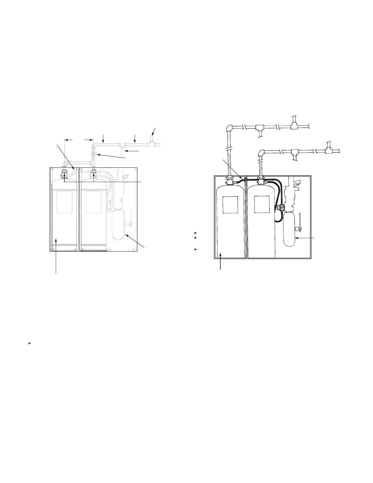
Distribution Piping Requirements – 6.0 Gallon Manifolded
System (Continued)
This conguration consists of two 3 gallon tanks. Both tanks are
connected to a common manifold tee and are pressurized from
a single double tank (Part No. 73022) nitrogen cartridge in the
regulated release assembly. See Figure 4-136. Note: A tank
mounting bracket can be utilized instead of the tank/enclosure
assembly.
FIGURE 4-136
Distribution Piping Requirements – With Independent Pipe
Runs
Independent pipe runs can also be used with the regulated
release assembly and the tank/enclosure assembly or tank
mounting brackets. See Figure 4-137. When manifolding is not
used, each of the two 3 gallon tanks utilize the piping limitations
of a single tank system.
FIGURE 4-137
000786
Note: If an expellant gas hose is to be used for a second tank
in an adjacent tank enclosure or tank bracket assembly, the
second tank will need to be installed on the left side of the
AUTOMAN Regulated Release, with the outlets a maximum of
8.5 in. (215 mm) from center to center, similar to the manifolded
system in Figure 4-136. Otherwise, the second tank will require
1/4 in. NPT pipe instead of expellant gas hose.
NOTE 1: THE PIPE CONNECTION FROM TANK CENTER TO TANK
CENTER CANNOT EXCEED 8 1/2 IN. (215 mm). ALSO, OEM
RELEASE/BRACKET ASSEMBLY CAN BE UTILIZED WHEN
MANIFOLDING 3.0 GALLON TANK.
NOTE 2: ONLY 3 GALLON TANKS CAN BE MANIFOLDED.
NOTE 3: THE BURST DISC THAT IS PART OF THE TANK ADAPTOR/
BURST DISC ASSEMBLY MUST BE REMOVED AND
MODIFIED. SEPARATE THE ALUMINUM DISC MATERIAL
FROM THE PLASTIC GASKET. DISCARD THE ALUMINUM
DISC MATERIAL AND REINSTALL THE PLASTIC GASKET
BACK INTO THE TANK ADAPTOR/BURST DISC ASSEMBLY.
NOTE 4: THE IN-LINE BURST DISC ASSEMBLY (PART NO. 416970)
IS TO BE MOUNTED AS CLOSE TO THE TANK OUTLET AS
POSSIBLE. AFTER SYSTEM DISCHARGE, THE ASSEMBLY
MUST BE DISASSEMBLED AND A NEW BURST DISC
INSTALLED.
008127
USE HOSE/
GROMMET
PACKAGE
(PART NO.
418511)
SEE
NOTE
NO. 1
3/8 IN.
SUPPLY
3/8 IN.
SUPPLY
3/8 IN.
BRANCH
3/8 IN BRANCH
DOUBLE TANK
NITROGEN
CARTRIDGE OR
(LT-A-101-30
CARTRIDGE –
REGULATED
ACTUATOR ONLY)
IN-LINE BURST DISC
ASSEMBLY – SEE NOTE NO. 4
REMOVE
BURST DISC –
SEE NOTE NO. 3
3.0 GALLON REGULATED RELEASE
ASSEMBLY OR 3.0 GALLON REGULATED
ACTUATOR ASSEMBLY
TANK/ENCLOSURE
ASSEMBLY
3.0
GALLON
TANK
3.0
GALLON
TANK
HOSE/
GROMMET
PACKAGE
(PART NO.
418511)
3.0 GALLON
TANK
3.0 GALLON
TANK
DOUBLE TANK
NITROGEN
CARTRIDGE
OR LT-A-101-30
CARTRIDGE
(LT-A-101-30
CARTRIDGE –
REGULATED
ACTUATOR ONLY)
REGULATED RELEASE ASSEMBLY OR
REGULATED ACTUATOR ASSEMBLY
TANK/ENCLOSURE
ASSEMBLY

 Loading...