SECTION 5 – INSTALLATION INSTRUCTIONS
UL EX3470 ULC EX3470
2014-SEP-01 REV. 11 PAGE 5-43
R-102 Restaurant Fire Suppression Manual
WIRING 24VDC REGULATED RELEASE ASSEMBLY
CAUTION
Do not install cartridge or remove tank assembly unless release
is cocked and ring pin is in place. Failure to comply may result
in accidental system actuation.
If the following occurs during installation, the solenoid for the
releasing assembly may be damaged, rendering the system
inoperable.
1. If the release is electrically tripped (fired) with the ring pin
inserted such that the release mechanism is pinned in the
cocked position.
2. The lever arm of the mounted switch is bent such that the
switch does not operate when the release roll pin is bottomed
out in the fired position.
3. Trying to recock the release mechanism while power is
applied to the release through the alarm contacts.
For complete recharging, inspection, and maintenance instruc-
tions, refer to applicable fire suppression system manual.
!
WARNING
Take extreme care when wiring release assembly. Failure to
comply may cause an electrical shock, resulting in possible
serious injury or death.
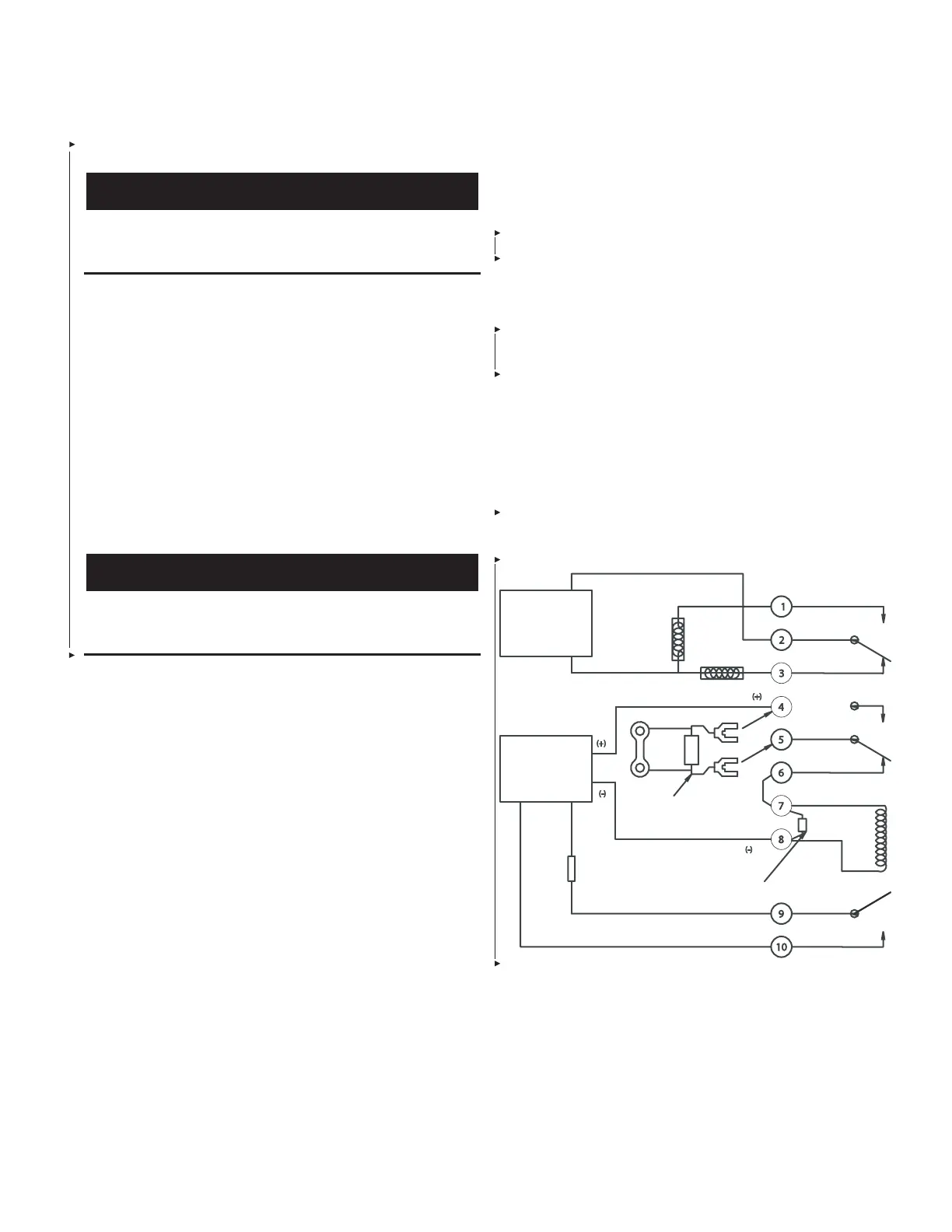
Refer to the following notes and wiring diagram for instruction on
wiring the 24VDC regulated release assembly.
Notes:
1. To be connected to a nominal 24VDC releasing circuit.
Input power: 750 mA at 24VDC nominal (1.02 at 30VDC
maximum).
2. Polarization: Observe polarity when connected to a release
circuit; Terminal 4 positive, Terminal 8 negative.
3. All interconnecting wiring number 14 - 18 AWG.
4. S
1
and S
2
contact ratings: 20A, 125/250 VAC 2 HP, 250 VAC
1 HP, 125 VAC.
5. SOL
1
coil resistance: 28 OHMS +/- 10% at 77 °F (25 °C).
6. Install the in-line supervisory device SD
x
across terminals
No. 4 and No. 5. Refer to the releasing panel installation
instructions for supervisory device requirements. If an in-line
supervisory device is not required, install jumper J
2
across
terminals No. 4 and No. 5.
7. S
3
contact ratings: 24VDC, 240mA maximum.
THESE SWITCH CONTACTS TRANSFER UPON
ACTUATION OF RELEASE
HIGH
ACCESSORY
POWER
SOURCE
LOW
*
TB
1
**
UL LISTED
SUPERVISED
RELEASING
CONTROL UNIT
S
1
NC
SD
X
OR
TZ
1
J
1
SOL
1
NC
S
2
VOLTAGE
TRANSIENT
SUPPRESSOR
* AUXILIARY ALARMING DEVICES, SEE S
1
RATINGS
** FUEL SHUT-OFF VALVE, BLOWER MOTOR, DOOR CLOSER, ETC., SEE S
1
RATINGS.
IN-LINE
SUPERVISORY DEVICE
FIGURE 5-125
008468
 Loading...
