SECTION 5 – INSTALLATION INSTRUCTIONS
UL EX3470 ULC EX3470
PAGE 5-42 REV. 11 2014-SEP-01
R-102 Restaurant Fire Suppression Manual
ELECTRICAL SWITCH REQUIREMENTS (Continued)
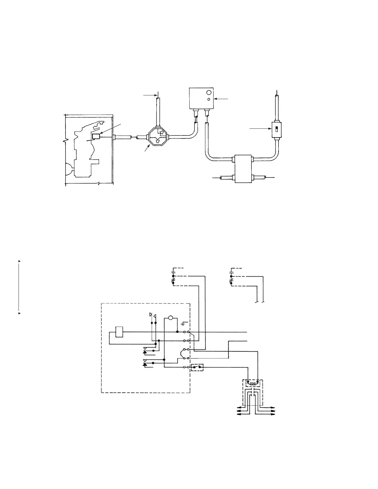
Electric (110 VAC/60 Hz) Application with Customer Supplied Contactor and Heating Element Load, and Power Supply Switch
INSTALLATION OVERVIEW
WIRING SCHEMATIC
WIRING SCHEMATIC – RELAY PART NO. 426151
RELAY COIL
ANSUL SNAP-ACTION SWITCH
(SWITCH CONTACTS SHOWN WITH AUTOMAN
RELEASE IN THE COCKED POSITION)
BLACK
RED
BROWN
RESET
B
A
RED
POWER
INDICATOR
GND
SCREW
5
4
3
2
1
6
9
3
4
7
1
MANUAL RESET RELAY
(PART NO. 426151)
ELECTRIC RATING
1/3 HP, 10 Amp, 120 VAC
1/2 HP, 10 Amp, 240 VAC
13 Amp, 28 VDC
SWITCH OR THERMOSTAT
(CUSTOMER SUPPLIED)
TO HEATING
ELEMENT LOAD
L2 NEUTRAL
L1 HOT
110 VAC/60HZ
CONTACTOR
(CUSTOMER SUPPLIED)
TO POWER SUPPLY
220V/440V
002461
NOTE:
1. ______________ DENOTES FIELD INSTALLATION.
2. __ __ __ __ __ DENOTES FACTORY INSTALLATION.
3. CONTRACTORS: “UL LISTED ENCLOSED INDUSTRIAL CONTROL EQUIPMENT OR MAGNETIC SWITCH HAVING A RATING MATCHING THAT OF THE
COOKING APPLIANCE COIL, 110V/60HZ.”
4. DO NOT USE BLACK WIRE ON SNAP-ACTION SWITCH IN NORMAL INSTALLATION. BLACK WIRE TO BE USED ONLY
FOR EXTRANEOUS ALARM, LIGHT CIRCUITS, ETC.
FIGURE 5-124
POWER SOURCE
ELECTRIC
SNAP-ACTION
SWITCH
JUNCTION BOX
(NOT SUPPLIED BY TYCO)
MANUAL RESET
RELAY
SWITCH OR
THERMOSTAT
(CUSTOMER SUPPLIED)
CONTACTOR
(CUSTOMER SUPPLIED)
000279
UPPER SWITCH LOWER SWITCH
TO
4
TO
3
BROWN
RED
BLACK
 Loading...
