SECTION 4 – SYSTEM DESIGN
UL EX3470 ULC EX3470
2014-SEP-01 REV. 11 PAGE 4-63
R-102 Restaurant Fire Suppression Manual
ACTUATION AND EXPELLENT GAS LINE REQUIREMENTS
(Continued)
Expellant Gas Line
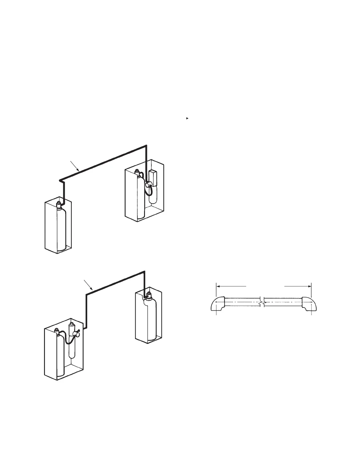
1. The expellant gas line is installed from the regulated release
mechanism in double, three, and multiple-tank systems,
and from the regulated actuator assembly in multiple-tank
systems. The expellant gas line is the piping and/or hose
between the regulator and the tank-enclosure/tank-bracket
assembly. The total length of the expellant gas line from
the regulated release mechanism or each regulated actu-
ator assembly must not exceed 30 ft (9.1 m) when using
a “double-tank” cartridge, an LT-A-101-30 Cartridge, or a
101-30 Cartridge. See Figures 4-124 and 4-125.
FIGURE 4-124
000776
FIGURE 4-125
000777
2. A combined total of nine ttings may be used in these lines,
eight 90° elbows and one tee. Two 45° elbows equal one
90° elbow.
3. If two tanks are connected to the regulated release
assembly in a multiple-tank system arrangement, the total
combined length of the actuation and expellant gas lines
must not exceed 30 ft (9.1 m) when using a “double-tank”
nitrogen cartridge, an LT-A-101-30 nitrogen cartridge, or a
101-30 carbon dioxide cartridge. See Figure 4-122.
4. If three 3.0 gallon tanks are connected to the regulator in
either a regulated release or regulated actuator assembly,
only factory supplied expellant gas hose assemblies will
be utilized. Refer to Distribution Piping Requirements – 9.0
Gallon System, page 4-70 for additional design requirements.
DISTRIBUTION PIPING REQUIREMENTS
Once the nozzle placement and quantity of tanks has been
determined, it is then necessary to determine the piping cong-
urations between the tank adaptor and each discharge nozzle.
This section contains the guidelines and limitations for designing
the distribution piping so that the liquid agent will discharge from
the nozzles at a proper ow rate. These limitations should also
be referred to when selecting the mounting location for the regu-
lated release mechanism and agent tank.
General Piping Requirements
1. All R-102 system piping is straight line. Therefore, the need
for critical lengths and balancing is minimized.
2. Two 45° elbows count as one 90° elbow.
3. Each branch line includes the tee or elbow leading to it, and
all ttings within the branch line itself.
4. The minimum piping length of Schedule 40, 3/8 in. pipe from
the tank outlet to any nozzle protecting a range, fryer, or wok
must be 6 ft (1.9 m).
5. Pipe lengths are measured from center of tting to center of
tting. See Figure 4-126.
FIGURE 4-126
000778
6. All distribution piping must be 3/8 in. Schedule 40 black iron,
chrome-plated, or stainless steel. Do not use hot dipped
galvanized pipe on the distribution piping.
7. All threaded connections located in and above the protected
area must be sealed with pipe tape. Tape should be applied
to male threads only. Make certain tape does not extend over
the end of the thread, as this could cause possible blockage
of the agent distribution.
8. Before installing blow-off caps on nozzles, apply a small
amount of Dow Corning No. 111 silicone grease across the
opening in the nozzle tip and also a small amount coating the
exterior of the blow-off cap. This will help keep cooking grease
from building up on the cap.
9. Tees used in the distribution piping can be used as thru tees,
side outlet tees, or bull tees.
EXPELLANT GAS LINE
MAXIMUM LENGTH – 30 FT (9.1 m);
MAXIMUM NO. OF FITTINGS – 9
AUTOMAN REGULATED
RELEASE ASSEMBLY
EXPELLANT GAS LINE
MAXIMUM LENGTH – 30 FT (9.1 m);
MAXIMUM NO. OF FITTINGS – 9
REGULATED ACTUATOR
ASSEMBLY
CENTER TO CENTER

 Loading...