SECTION 5 – INSTALLATION INSTRUCTIONS
UL EX3470 ULC EX3470
PAGE 5-22 REV. 11 2014-SEP-01
R-102 Restaurant Fire Suppression Manual
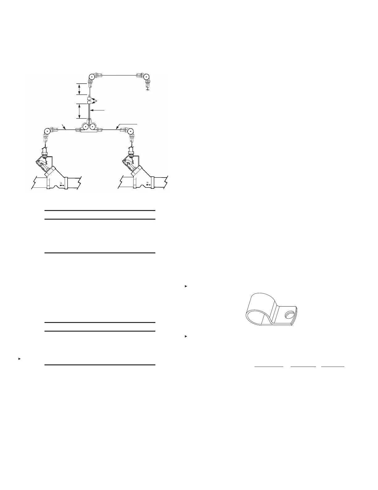
INSTALLING MECHANICAL GAS VALVE (Continued)
MINIMUM OF 6 IN.
(153 mm)
MINIMUM OF 6 IN.
(153 mm)
SPLICED WIRE ROPE
CONTINUOUS
WIRE ROPE
PULLEY TEE
(PART NO. 427929) ONLY
TWO OVAL SLEEVES
(PART NO. 4596)
NOTE: EITHER BOTH MUST BE
GAS VALVES OR BOTH MUST
BE PULL STATIONS. MIXING IS
NOT ALLOWED.
NO ELBOWS ALLOWED
WHERE TWO WIRE ROPES
ARE PRESENT
ONE AIR CYLINDER – TWO MECHANICAL GAS VALVES
TO AIR CYLINDER IN
AUTOMAN
RELEASE
FIGURE 5-50
008394
NOTICE
When connecting two mechanical gas valves
to one air cylinder, make certain both gas
valves properly operate (close) when the air
cylinder rod is in the down (operated) position.
INSTALLATION OF REMOTE MANUAL PULL STATION OR
MECHANICAL GAS VALVE UTILIZING FLEXIBLE CONDUIT
Flexible conduit allows for quicker installations and the conve-
nience of being able to route the cable over, under and around
obstacles.
Flexible conduit can be used as a substitute for standard EMT
conduit or can be used with EMT conduit.
NOTICE
Flexible conduit can be used only with NEW
Remote Pull Station (Part No. 434618) and
mechanical gas valve installations. Flexible
conduit is intended for indoor use ONLY.
These instructions address the components and installation of
both the pull station (Part No. 434618) and the flexible conduit.
Design Requirements
• Flexible conduit cannot be utilized in detection systems.
• Flexible conduit inserts (Part No. 434347) can ONLY be used
with the flexible conduit system.
• The maximum distance from an AUTOMAN release to a pull
station is 140 ft (42.6 m) with a maximum of 360° (for example,
3-90° and 2-45° bends, 2-90° and 4-45° bends, etc.) bends in
the flexible conduit, one pulley tee (refer to pages 5-31 through
5-33 for detailed splicing instructions), two splices, and 15
pulley elbows.
Note: When installing flexible conduit, make sure to feed wire
rope through conduit directly from the spool. DO NOT pre-cut
wire rope. Feeding pre-cut rope through flexible conduit will
cause excessive kinks in the rope, making it difficult to install.
• The maximum distance from an AUTOMAN release to a
mechanical gas valve is 75 ft (22.8 m) with a maximum of
4-90° bends in the flexible conduit and 4 pulley elbows.
• Any portion of the flexible conduit system can be substituted
with EMT conduit provided the proper connections are used
to join the two types of conduit.
• All bends in the flexible conduit system must have a minimum
bend diameter of 6 in. (153 mm).
• When the flexible conduit is used to make 90° bends between
an AUTOMAN release and a mechanical gas valve, the bends
must start at the gas valve. No pulley elbows can be used
between the bends. If more than 360° of bends are needed,
then pulley elbows can be used.
• When the flexible conduit is used to make 90° bends between
an AUTOMAN release and a pull station, the bends must start
at the AUTOMAN release. No pulley elbows can be used
between the bends. If more than 360° of bends are needed,
then pulley elbows can be used.
• When not utilizing a conduit offset 2-45° bends in the flexible
conduit are allowed between the strain relief fitting on top of
the AUTOMAN release, and the location where the flexible
conduit is supported.
• When installing flexible conduit, conduit should be secured at
intervals not to exceed 5 ft (1.5 m) and before and after each
bend. Flexible conduit CANNOT slide in the clamp(s) used for
mounting. Make certain mounting clamp(s) do not pinch the
conduit. The following style clamp (‘P’ clip) (Part No. 436150)
is a suitable type for use on flexible conduit. See Figure 5-51.
FIGURE 5-51
008141
TABLE 1
Mechanical
Manual Pull Gas Valve Detection
90° Cable Bends 4 4 N/A
Bend Diameter – in. (mm) 6 (153) 6 (153) N/A
Mechanical Corner Pulley 15 4 N/A
Conduit Secured Max. ft (m) 5 (1.5) 5 (1.5) N/A
Conduit Max. Length ft (m) 140 (42.6) 75 (22.8) N/A
Conduit Offset / 2-45° Bends 1 0 N/A
(Only between strain relief
fitting and support location)
Pulley Tees 1 0 N/A
Splices 2 0 N/A

 Loading...