SPECIFIC APPLICATION BY MODEL (Continued)
DUKE Electric Broiler – Model FBB – Low Proximity
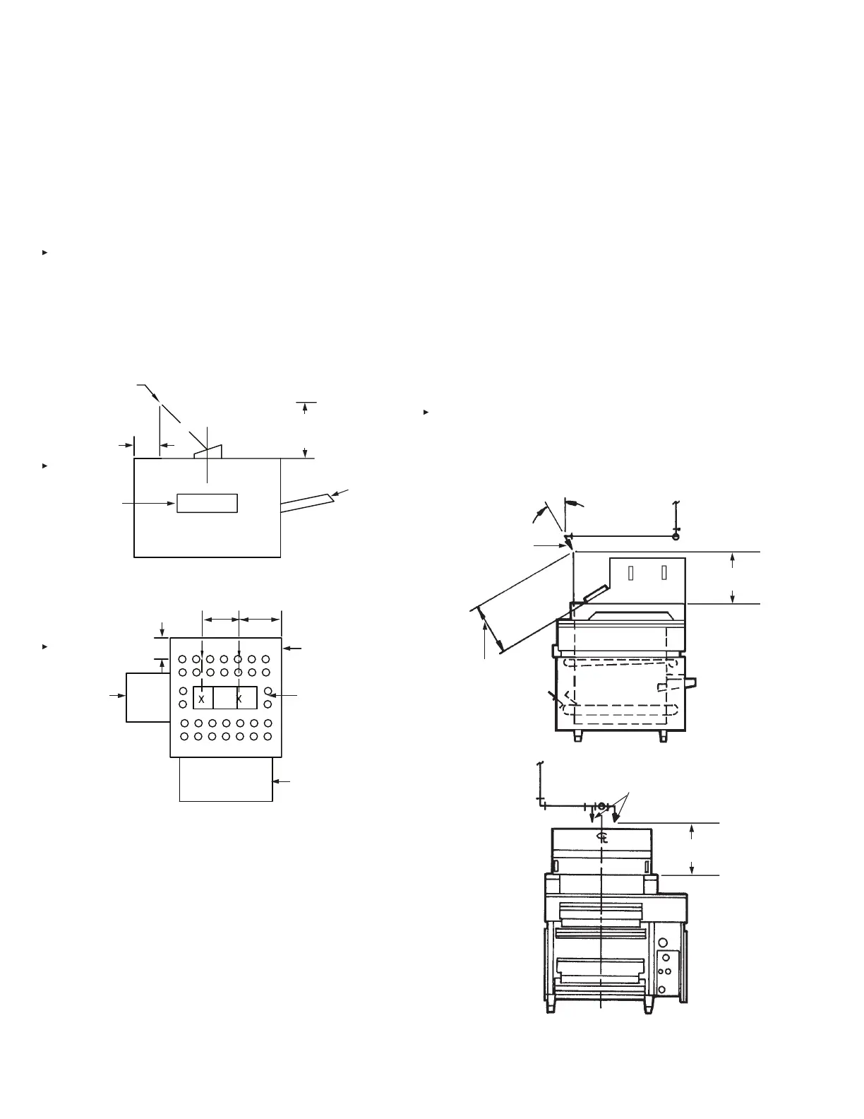
DUKE Electric Broiler with or without Catalyst View
Nozzle Quantity/Type: Two 245 nozzles
Nozzle Height: 8 in. (203 mm) to 15 in. (381 mm)
Nozzle Location:
6.5 in. (165 mm) from edge of appliance that
impedance plate is angled toward
First nozzle positioned 17.5 in. (444 mm)
from right side of broiler (facing broiler)
Second nozzle positioned 15 in. (381 mm)
from rst nozzle
See Figure 4-87
Nozzle Aiming Point: Aimed at center of opening
FIGURE 4-87
Nieco Broiler Model 940, 962 or 960 With Catalytic
Converter Protection
Note: Nieco broilers without catalytic converters use standard
chain broiler protection options.
Certain models of the Nieco broiler (Models 940, 962, and 960)
are equipped with a catalytic converter to comply with new clean
air laws. Because of the converter, it is necessary to protect
these broilers in a special way. The guidelines for protecting
these broilers are as follows:
– The maximum internal broiling area is 29 in. x 23.5 in.
(737 mm x 596 mm).
– An R-102 3-gallon system with a maximum of six ow
numbers, must be used for protection of each broiler, includ-
ing plenum and duct.
– Each individual broiler must be protected with a minimum of
two 1N nozzles. The nozzles must be located as shown in
Figure 4-88.
– The broiler must be tted with two 1 in. (25 mm) high agent
barriers on the angled surface of the broiler. If these have
not been completed by the equipment supplier, they must be
added in the eld.
FIGURE 4-88
008365
PRODUCT
INPUT
PRODUCT
OUTPUT
FRONT
BACK
SIDE VIEW
(2) – 245 NOZZLE
6 1/2 IN. (165 mm)
FROM EDGE OF
APPLIANCE THAT
IMPEDANCE
PLATE IS ANGLED
TOWARD
8 IN. (203 mm) TO
15 IN. (381 mm)
NOZZLE HEIGHT
PRODUCT
INPUT
PERFORATED
GRILL
CENTER
DUCT
PRODUCT
OUTPUT
TOP VIEW
6 1/2 IN. (165 mm) FROM
EDGE OF APPLIANCE
THAT IMPEDANCE PLATE
IS ANGLED TOWARD
(SEE SIDE VIEW)
008368
15 IN.
(381 mm)
17 1/2 IN.
(444 mm)
000250
(2) 1N NOZZLES
12 IN. TO 13 IN.
(305 mm to 330 mm)
30°
14.25 ± 1 IN.
(362 mm ± 25 mm)
LOCATE NOZZLES 2 13/16 IN. (71 mm) ON
EACH SIDE OF BROILER CENTER LINE
14.25 ± 1 IN.
(362 mm ± 25 mm)
000774
SECTION 4 – SYSTEM DESIGN
UL EX3470 ULC EX3470
PAGE 4-44 REV. 11 2014-SEP-01
R-102 Restaurant Fire Suppression Manual
 Loading...
