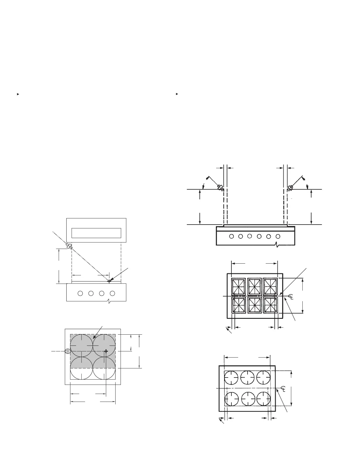
Range Protection 1N (1-Flow) Nozzle – Low Proximity
Application
15 in. to 20 in. (381 mm to 508 m) above the cooking surface.
The low proximity 1-ow nozzle application for the protection of
ranges requires the 1N nozzle.
The nozzle is stamped with 1N indicating that it is a one-ow
nozzle and must be counted as one ow number,
When using the 1N nozzle for low proximity range protection
with or without obstruction, the maximum length of the burner
grates being protected must not be exceed 24 in. (609 mm)
length, aimed along a centerline to a point 20 in. (508 mm) from
the end of the length, protecting a maximum width of 18 in. (457
mm).
When protecting a range, the 1N nozzle must be located a
maximum of 9 in. (228 mm) from each burner grate centerline
and must be positioned above the edge of the hazard area to be
protected.
The 1N nozzle tip must be positioned at or below the obstruc-
tion, if present. The protected area begins at the point straight
down from the nozzle tip. The nozzle can be placed at the side
of the range aimed either left or right, or can be placed in the
front or back of the range. See Figures 4-33 and 4-34 for nozzle
location details.
FIGURE 4-33
FIGURE 4-34
Range Protection Two 290 (2-Flow) Nozzles – Low
Proximity Application
15 in. to 20 in. (381 mm to 508 mm) above the cooking surface.
The low proximity 2-ow application requires the use of two 290
nozzles.
Both nozzles are stamped with 290 indicating they are two ow
nozzles and must be counted together for a total of four ow
numbers.
Two 290 nozzles will protect a cooking area of 1008 in.
2
(65032 mm
2
) with a maximum dimension of 36 in. (914 mm).
When using two of these nozzles for low proximity range protec-
tion, the nozzles must be positioned along the cooking surface
perimeter to 1.5 in. (38 mm) inside the perimeter, and aimed at
a 45° angle along the longitudinal centerline of the range. See
Figures 4-35 and 4-36.
FIGURE 4-35
FIGURE 4-36
15 – 20 IN.
(381 – 508 mm)
20 IN.
(508 mm)
007924
AIM
POINT
24 IN.
(609 mm)
20 IN.
(508 mm)
18 IN.
(457 mm)
9 IN.
(228 mm)
007925
AIM POINT
PROTECTED AREA
000240
290 NOZZLE TIP LOCATION
0 – 1.5 IN. (38 mm) IN FROM EDGE
OF COOKING SURFACE
290 NOZZLE TIP
LOCATION CENTER OF
COOKING SURFACE
± 2 IN. (50 mm)
COOKING
AREA
COOKING
AREA
000239
290 NOZZLE TIP LOCATION
0 – 1.5 IN. (38 mm) IN FROM EDGE
OF COOKING SURFACE
290 NOZZLE TIP
LOCATION CENTER OF
COOKING SURFACE
± 2 IN. (50 mm)
COOKING
AREA
LONGITUDINAL
CENTERLINE
COOKING
AREA
15 IN. TO 20 IN.
(381 to 508 mm)
MAXIMUM
15 IN. TO 20 IN.
(381 to 508 mm)
MAXIMUM
45°
45°
290 NOZZLE TIP
LOCATION 0 – 1.5 IN.
(0 – 38 mm)
IN FROM EDGE OF
COOKING SURFACE
002276
SECTION 4 – SYSTEM DESIGN
UL EX3470 ULC EX3470
PAGE 4-16 REV. 11 2014-SEP-01
R-102 Restaurant Fire Suppression Manual

 Loading...