SECTION 4 – SYSTEM DESIGN
UL EX3470 ULC EX3470
PAGE 4-34 REV. 11 2014-SEP-01
R-102 Restaurant Fire Suppression Manual
SPECIFIC APPLICATION BY MODEL (Continued)
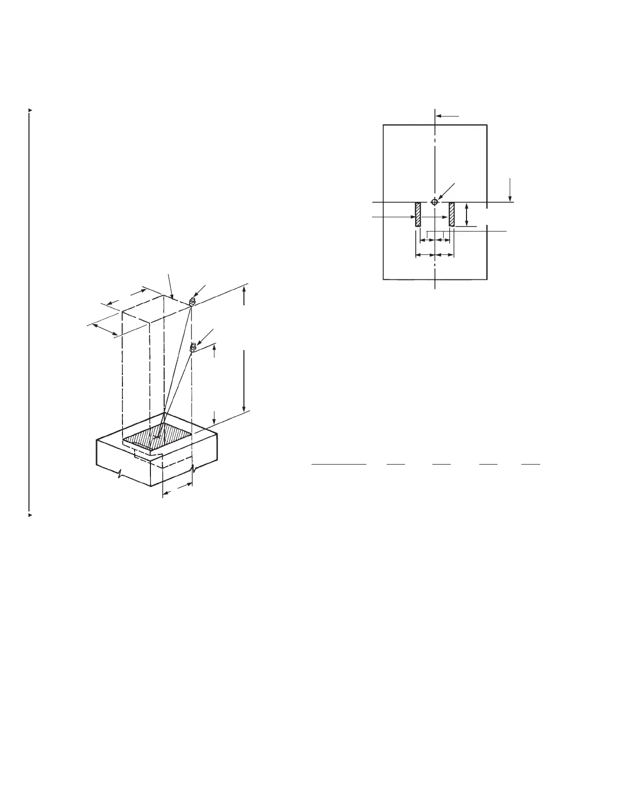
Frymaster Energy Efcient RE 14 Fryer
This electric fryer can be protected with either a single 230
nozzle located 27 to 47 in. (685 mm to 1193 mm) above the top
surface of the fryer or with a single 245 nozzle located 20 to 27
in. (508 mm to 685 mm) above the top surface of the fryer.
Either nozzle must be located anywhere along or within the
perimeter of the cooking surface and aimed at the midpoint.
See Figure 4-70. The maximum size of the fry pot (without drip
board) is 14 x 15 1/2 in. (355 mm x 393 mm) and the maximum
size of the cooking surface (with drip board) is 14 x 20 7/8 in.
(355 mm x 530 mm). The vat may be divided in half to make
two split vats.
FIGURE 4-70
McDonald Fryer (Nozzle Heights of Less Than 20 in.
(508 mm))
When the 245 nozzle is used to protect McDonald’s fryers at
heights less than 20 in. (508 mm) above the top of the fryer, the
following appliance and distribution piping rules shall apply:
1. Each McDonald’s gas or electric fryer shall be protected by
one 245 nozzle. The fryer vat dimensions for one full vat or
two split vats shall not exceed 14 in. x 15 in. (355 mm x 381
mm) without the dripboard and 14 in. x 21 in. (355 mm x 533
mm) with the dripboard.
The heat input rating of the fryer shall not exceed 122,000
BTU/HR.
The 245 nozzle shall be located 18 in. to 20 in. (457 mm to
508 mm) above the top of the fryer vat, 2 in. to 2 1/4 in.
(51 mm to 57 mm) to the right or left of the front-to-rear vat
centerline, and 0 to 3 1/4 in. (0 to 82 mm) forward of the
right-to-left vat centerline, and aimed at the vat center point.
See Figure 4-71.
FIGURE 4-71
002297
2. The distance between the start of the rst branch line and the
start of the last branch line shall not exceed 79 in. (2006 mm).
3. The total length of all branch lines shall not exceed 162 in.
(4114 mm).
4. The 3 gallon agent tank shall be elevated above the connec-
tions between the supply and branch lines.
5. The requirements of the following table shall not be
exceeded:
Duct Plenum Appliance
Supply Branch Branch Branch
Requirement Line Line Line Line
Pipe Size 3/8 in. 3/8 in. 3/8 in. 3/8 in.
Maximum Length 140 in. 67 in. 6 in. 42 in.
(3556 mm) (1701 mm) (152 mm) (1066 mm)
Minimum Length 81 in. 4 in. 4 in. 17 in.
(2057 mm) (101 mm) (101 mm) (431 mm)
Maximum 5 3 1 6
90° Elbows
Maximum Tees 0 1 1 1
Maximum Flow 11 2 1 2
Numbers
Minimum Flow 5 0 0 1/2
Numbers
230 NOZZLE TIP OR 245 NOZZLE TIP ANYWHERE ALONG OR WITHIN THE PERIMETER
OF THE COOKING SURFACE AND AIMED AT THE MIDPOINT.
20 7/8 IN.
(530 mm)
MAXIMUM
14 IN.
(355 mm)
MAXIMUM
230 NOZZLE
230 NOZZLE
27 IN. – 47 IN.
(685 mm –
1193 mm) ABOVE
TOP SURFACE
OF FRYER
245 NOZZLE
20 IN. – 27 IN.
(508 mm –
685 mm)
ABOVE TOP
SURFACE OF
FRYER
15 1/2 IN. (393 mm)
MAXIMUM
245
NOZZLE
FRONT-TO-REAR
VAT CENTERLINE
REAR
AIM
POINT
NOZZLE
LOCATION
ZONES
3 1/4 IN.
(82 mm)
2 1/4 IN.
(57 mm)
2 1/4 IN.
(57 mm)
2 IN.
(51 mm)
FRONT
RIGHT-TO-LEFT VAT
CENTERLINE

 Loading...