SECTION 5 – INSTALLATION INSTRUCTIONS
UL EX3470 ULC EX3470
2014-SEP-01 REV. 11 PAGE 5-17
R-102 Restaurant Fire Suppression Manual
INSTALLING REMOTE MANUAL PULL STATION
GENERAL INSTALLATION REQUIREMENTS
To install a remote manual pull station complete the following
steps:
1. Make certain that regulated release assembly enclosure
cover is detached and lock pin is properly inserted within the
regulated release mechanism.
NOTICE
Failure to follow these instructions may
lead to system actuation.
2. Verify that cartridge has been removed from regulated
release assembly and that the regulated release assembly
is in the cocked position.
If regulated release assembly does not have lock pin
inserted or cartridge removed, refer to the “Semi-Annual
Maintenance,” Page 8-1, in “Maintenance Examination”
section, and complete Steps 2 and 3 before completing the
following installation steps.
3. Select a convenient location in the path of egress for mount-
ing the pull station(s) to the wall. The pull station should
be installed at a height of 42 in. to 48 in. (1067 mm to
1219 mm) in accordance with the authority having jurisdic-
tion and the American Disabilities Act (ADA) requirements.
A maximum of two manual pull stations can be connected
to each AUTOMAN release.
INSTALLATION FOR REMOTE MANUAL PULL STATION
UTILIZING EMT CONDUIT ONLY
1. The total length of the wire rope used for each manual pull
station within a system must not exceed 150 ft (45.7 m).
The maximum number of pulley elbows that may be used
per each manual pull station is 20.
2. If junction box(es) is used, fasten a 4 in. (102 mm) junction
box to wall or in wall where pull station is to be mounted,
with mounting screws positioned so that when pull station
cover is positioned in place, the printing will appear right
side up and readable.
3. Install and secure 1/2 in. conduit, pulley tee (if required),
and pulley elbows from each pull station junction box to
regulated release assembly as necessary. See Figure 5-37.
See Figures 5-38 thru 5-40 for optional methods of installing
wire rope when utilizing a pulley tee.
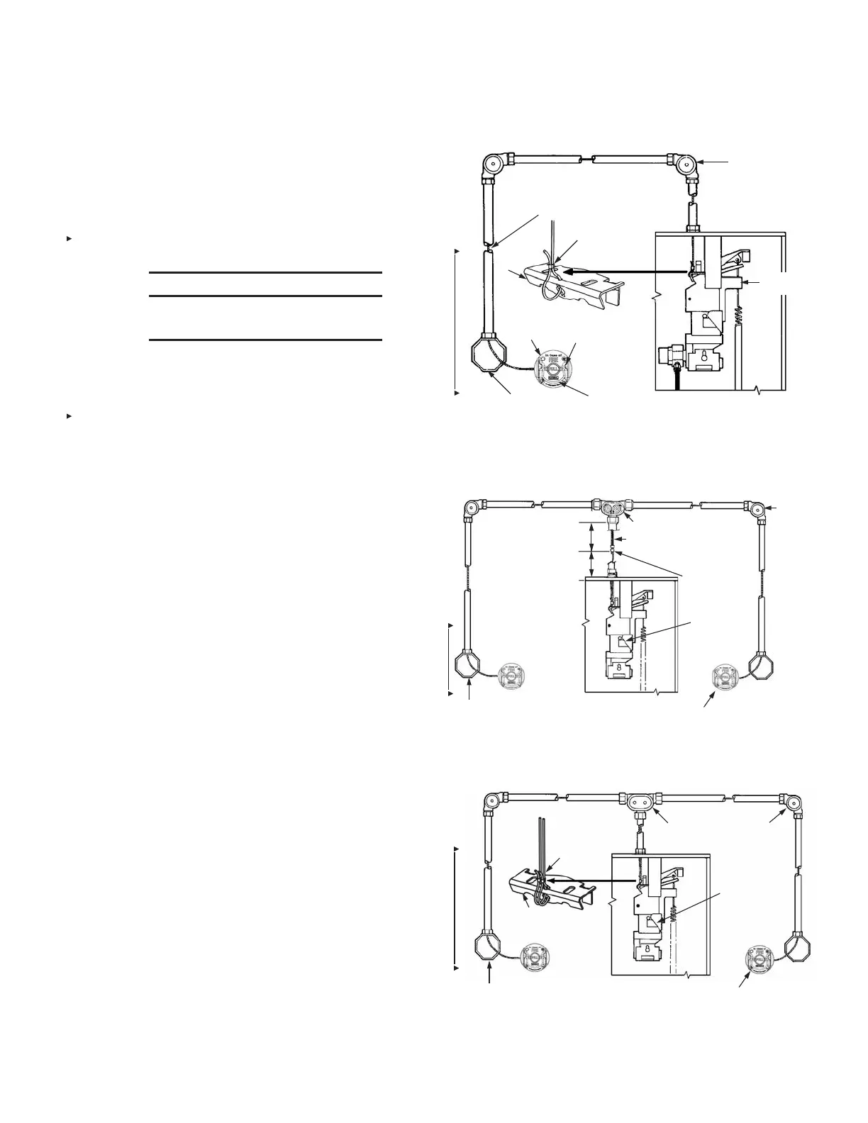
REMOTE MANUAL PULL STATION SINGLE APPLICATION
RELEASE
MECHANISM
PULLEY
ELBOW
WIRE ROPE
CABLE
LEVER
OVAL SLEEVE
REMOTE
MANUAL PULL
STATION
BREAK ROD
JUNCTION BOX
(SUPPLIED BY OTHERS)
RING HANDLE
FIGURE 5-37
009463
REMOTE MANUAL PULL STATION DUAL APPLICATION – OPTION 1
(ONE WIRE ROPE CONNECTED TO CABLE LEVER ASSEMBLY)
JUNCTION BOX
(SUPPLIED BY OTHERS))
PULLEY TEE
NO PULLEY ELBOWS
ALLOWED WHERE TWO WIRE
ROPES ARE PRESENT
USE TWO
OVAL SLEEVES
(PART NO.
4596)
PULLEY
ELBOW
RELEASE
MECHANISM
REMOTE
MANUAL PULL STATION
6 IN. (153 mm) MINIMUM
FROM CRIMP SLEEVE
TO PULLEY TEE
2 IN. (51 mm) MINIMUM
FROM CRIMP SLEEVE
TO COMPRESSION
FITTING
FIGURE 5-38
009464
REMOTE MANUAL PULL STATION DUAL APPLICATION – OPTION 2
(TWO WIRE ROPES CONNECTED TO CABLE LEVER ASSEMBLY)
OVAL
SLEEVE
CABLE
LEVER
JUNCTION BOX
(SUPPLIED BY OTHERS)
PULLEY TEE
PULLEY
ELBOW
RELEASE
MECHANISM
REMOTE
MANUAL PULL STATION
FIGURE 5-39
009465

 Loading...