SECTION 5 – INSTALLATION INSTRUCTIONS
UL EX3470 ULC EX3470
PAGE 5-36 REV. 11 2014-SEP-01
R-102 Restaurant Fire Suppression Manual
INSTALLING ELECTRICAL SWITCHES
The procedure for field installing an electric (snap-action) switch
is as follows:
!
CAUTION
Unused wire leads will become “hot” when the system is
operated. Failure to adequately cover exposed wire end(s) will
cause electric shock if touched.
!
CAUTION
Before working on any electrical wiring, make certain main
power has been disconnected. Failure to disconnect main
power could cause personal injury or death if contact is made
with energized wires.
NOTICE
Except for the Alarm Initiating Switch, all
electrical wiring connections are to be made
outside the AUTOMAN release enclosure in
suitable enclosures in accordance with local
jurisdiction requirements.
1. Make certain that regulated release assembly enclosure
cover is detached with lock pin properly inserted within the
regulated release mechanism.
NOTICE
Failure to follow these instructions may lead
to system actuation.
2. Verify that cartridge has been removed from regulated
release assembly and that the regulated release mech-
anism is in the cocked position. If regulated release
mechanism does not have lock pin inserted or cartridge
removed, refer to “Semi-Annual Maintenance,” Page 8-1, in
“Maintenance Exam ination” section, and complete Steps 2
and 3 before completing the following installation steps.
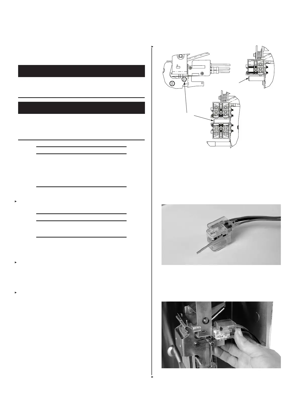
If regulated release mechanism has a factory installed sole-
noid, it will also have two factory installed switches.
FIGURE 5-113
001621
3. Install one or two of the electrical (snap-action) switches into
the switch cover for the upper tab of the switch mounting
bracket. See Figure 5-114.
Note: When applicable, always place the low voltage alarm
initiating switch(es) on the upper tab of the switch mounting
bracket. Never place low voltage alarm initiating switch(es)
on the lower tab of the switch mounting bracket.
FIGURE 5-114
009128
4. Slide switch cover onto the upper tab of the switch mounting
bracket, ensuring that the tab slides into the channels on the
back side of the switch cover, until the screw holes line up.
See Figure 5-115.
FIGURE 5-115
009129
TRIP LEVER PIN
TRIP LEVER PIN
 Loading...
