SECTION 5 – INSTALLATION INSTRUCTIONS
UL EX3470 ULC EX3470
2014-SEP-01 REV. 11 PAGE 5-37
R-102 Restaurant Fire Suppression Manual
8. Slide switch cover onto the lower tab of the switch mounting
bracket, ensuring that the tab slides into the channels on the
back side of the switch cover, until the screw holes line up.
See Figure 5-118.
FIGURE 5-118
009131
9. Install two switch mounting screws and nuts, ensuring that
the screws pass through the holes in the cover, though the
mounting holes in each of the switches, and through the
holes in the mounting bracket tab. Tighten screws securely.
Note: To meet UL requirements, the screws and nuts must
be installed. The switch cover is not intended to secure the
switches to the bracket.
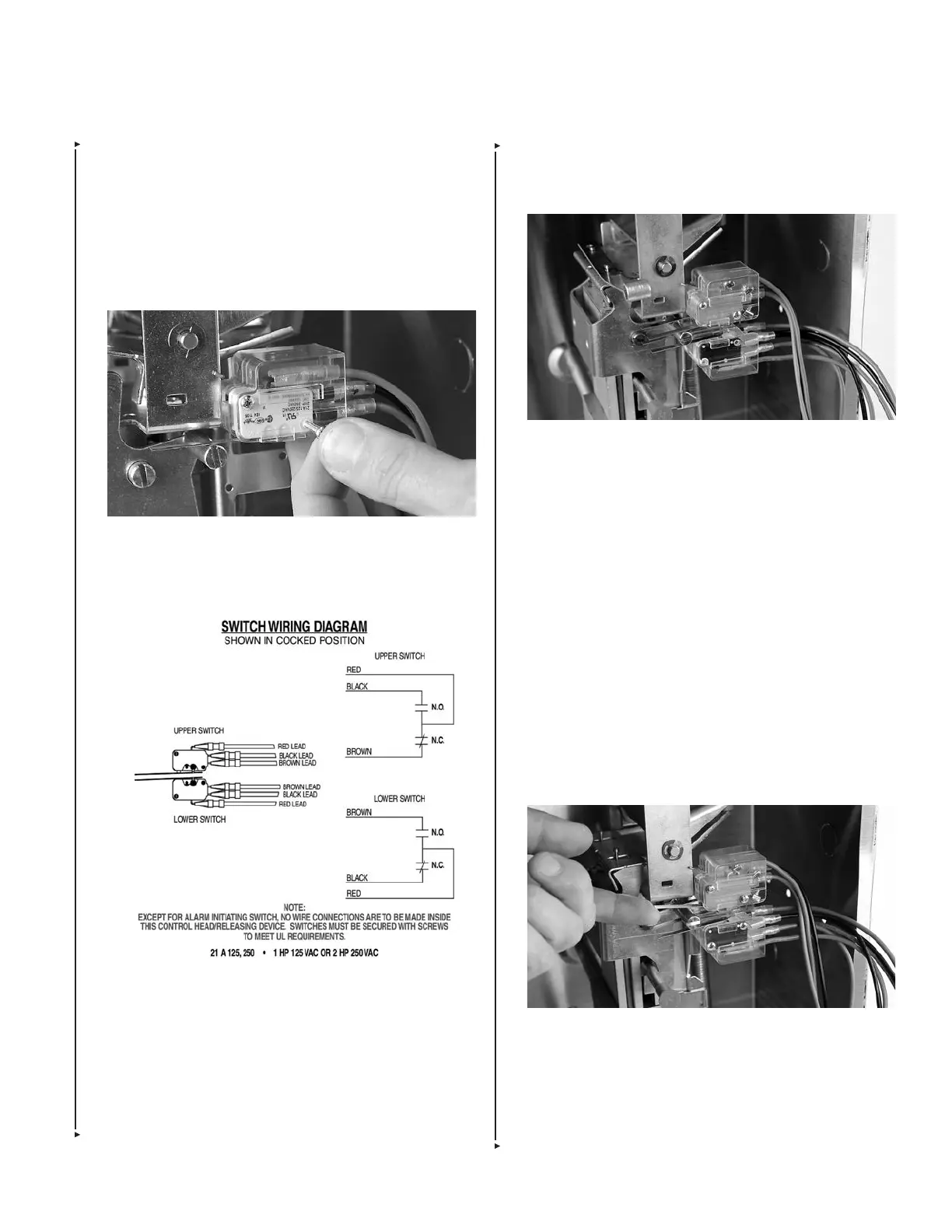
10. Wire the lower switches according to the switch wiring
diagram provided with each release mechanism. See
Figure 5-117.
Note: All wiring to be performed by a certified individual(s).
11. Restore power to release assembly.
12. Before proceeding with Step 13, test electric (snap-action)
switches:
a. Remove lock pin. With the AUTOMAN release in the
cocked or ready position, press the lever of each switch up.
If the switch is working properly there should be an audible
click. See Figure 5-119.
FIGURE 5-119
009133
b. With the AUTOMAN release in the fired position, press
the lever of each switch up, there should be no audible
click.
When installing multiple switches, make certain all
switches transfer when the release operates. If they do
not, readjust their position.
INSTALLING ELECTRICAL SWITCHES (Continued)
5. Install two switch mounting screws and nuts, ensuring that
the screws pass through the holes in the cover, though
the mounting holes in each of the switches, and through
the holes in the mounting bracket tab. See Figure 5-116.
Tighten screws securely.
Note: To meet UL requirements, the screws and nuts must
be installed. The switch cover is not intended to secure the
switches to the bracket.
FIGURE 5-116
009130
6. Wire the upper switch(es) according to the switch wiring
diagram provided with each release mechanism. See
Figure 5-117.
FIGURE 5-117
009145
7. If necessary, install one or two of the snap-action switches
into the switch cover for the lower tab of the switch mount-
ing bracket. These switches will be oriented opposite of the
upper switch(es) so that the levers will appear on the top
side of the switch when mounted to the lower tab of the
switch mounting bracket.
Note: Never place low voltage alarm initiating switch(es) on
the lower tab of the switch mounting bracket.
 Loading...
