SECTION 5 – INSTALLATION INSTRUCTIONS
UL EX3470 ULC EX3470
PAGE 5-34 REV. 11 2014-SEP-01
R-102 Restaurant Fire Suppression Manual
INSTALLATION OF REMOTE MANUAL PULL STATION OR
MECHANICAL GAS VALVE UTILIZING FLEXIBLE CONDUIT
(Continued)
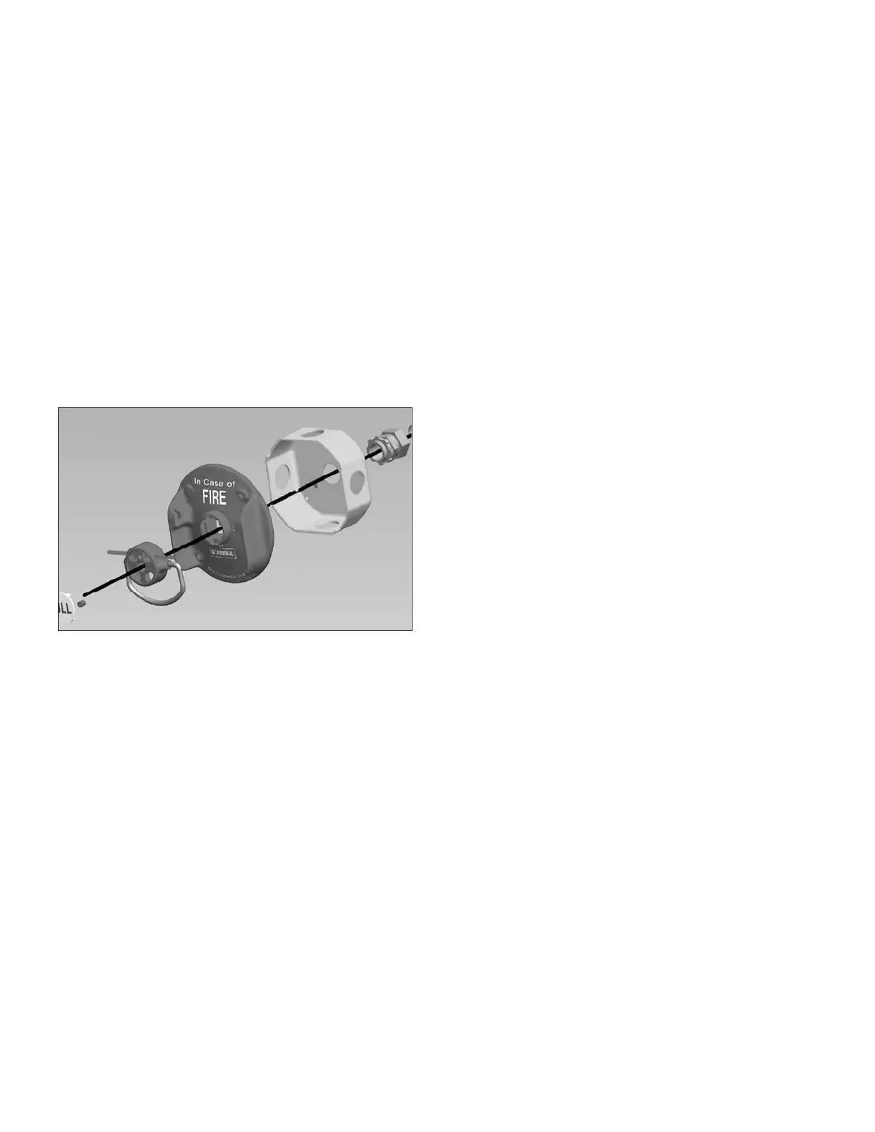
Pull Station Installation without Pulley Block Assembly
Note 1: When using this installation option, the distance
from the back of the faceplate and the connection to the 1/2
in. EMT conduit compression fitting must not exceed 6 in.
(152 mm).
Note 2: To provide for a straight run of wire rope from the pull
station, an octagonal junction box with a center knockout in the
back of the junction box will be needed. See Figure 5-111. If a
pre-fabricated box or enclosure is to be used, it must allow the
pull station face plate to be firmly attached to the box or enclo-
sure, with a hole or knockout suitable for a 1/2 in. EMT threaded
conduit compression connector to be installed directly in line
with the center of the pull station pull knob.
FIGURE 5-111
008415
1. Attach a 1/2 in. EMT conduit compression fitting (Part No.
55813) to the back center knock out of the junction box.
If something other than a junction box is to be utilized, a
method of securing the flexible conduit or EMT conduit
directly in line with the center of the pull station pull knob
must be used. This will ensure that in the event of manual
operation the wire rope, exiting the back of the pull station
faceplate, will be pulled straight out without binding or result-
ing in undue additional pull force due to friction loss.
2. Remove the block assembly from the pull station face plate.
Thread the wire rope from either flexible conduit or 1/2 in.
EMT conduit attached to the back of the junction box or
fabricated enclosure through the back side of the pull station
faceplate and through the pull knob.
3. Thread the wire rope through the stop sleeve (Part No.
26317) and leave approximately 1/4 in. to 3/8 in. (6.4 mm to
9.5 mm) extending past the sleeve.
4. Crimp the stop sleeve twice using the crimping tool National
Telephone Supply Co. Nicopress Sleeve Toll (Stock No,
51-C-887). Verify the sleeve is secure on the wire rope.
 Loading...
