SECTION 5 – INSTALLATION INSTRUCTIONS
UL EX3470 ULC EX3470
2014-SEP-01 REV. 11 PAGE 5-19
R-102 Restaurant Fire Suppression Manual
INSTALLING MECHANICAL GAS VALVE (Continued)
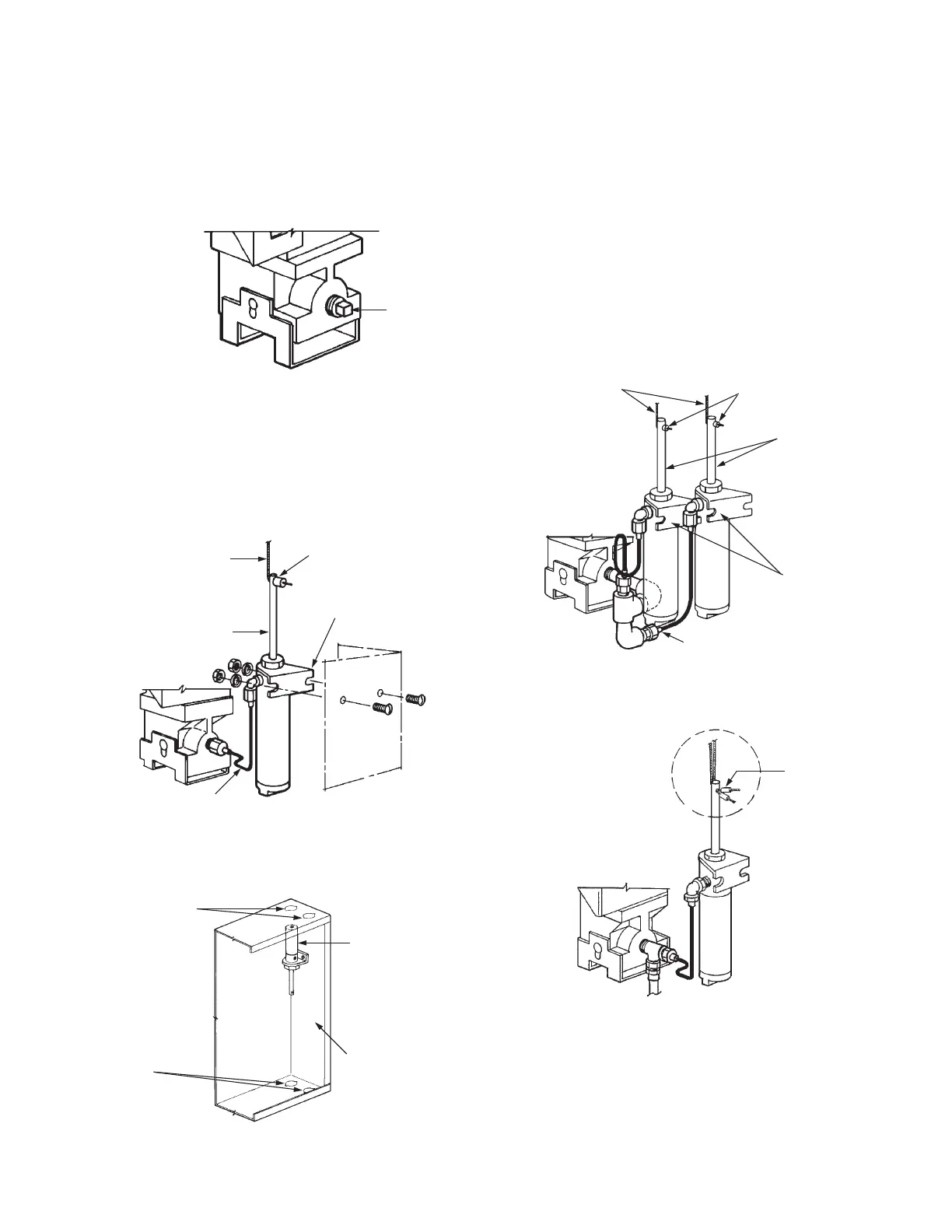
3. Remove plug from cartridge receiver. See Figure 5-42.
CARTRIDGE RECEIVER
PLUG
FIGURE 5-42
000339
4. Locate air cylinder and bracket assembly over the two 7/32
in. (5.6 mm) holes on right side of the enclosure. Assemble
with screws, lockwashers, and nuts. Wrench tighten. See
Figure 5-43. Air cylinder(s) can also be mounted in the
inverted position, allowing for direct exit out the knockout(s)
in the bottom of the enclosure. See Figure 5-44.
FOR MOUNTING ONE MECHANICAL GAS VALVE
WIRE ROPE
STOP SLEEVE
AIR CYLINDER
ROD
MOUNTING BRACKET
1/8 IN. COPPER
TUBING AND FITTINGS
FIGURE 5-43
000340
TOP KNOCKOUTS
BOTTOM
KNOCKOUTS
MECHANICAL
GAS VALVE
AIR CYLINDER
R-102 REGULATED
RELEASE
FIGURE 5-44
000341
Note: Two air cylinders are necessary only if the old style
pulley tee (Part No. 15342) is utilized. If new style pulley
tee (Part No. 427929) is utilized, only one air cylinder is
required. Individual wire ropes can be run from each gas
valve to a single air cylinder. See Figure 5-45.
5. To install second mechanical gas valve shut-off system,
locate second air cylinder and bracket assembly adjacent to
first assembly and over the two remaining 7/32 in. (6 mm)
holes provided on right side of the enclosure. Assemble
second cylinder with screws, lockwashers, and nuts as
required. Wrench tighten. See Figure 5-45.
WIRE ROPE
STOP
SLEEVES
AIR CYLINDER
RODS
MOUNTING
BRACKETS
1/8 IN. COPPER
TUBING AND FITTINGS
000342
SYSTEMS USING PULLEY TEE (PART NO. 15342)
004655
SYSTEMS USING PULLEY TEE (PART NO. 427929)
NOTE: NO ELBOWS ARE ALLOWED BETWEEN
AUTOMAN RELEASE AND PULLEY TEE
STOP
SLEEVES (2)
FIGURE 5-45
000342
 Loading...
