SECTION 5 – INSTALLATION INSTRUCTIONS
UL EX3470 ULC EX3470
PAGE 5-20 REV. 11 2014-SEP-01
R-102 Restaurant Fire Suppression Manual
INSTALLING MECHANICAL GAS VALVE (Continued)
6. Install the necessary 1/8 in. copper tubing and fittings for
each air cylinder to the accessories piping arrangement on
the regulated release mechanism. See Figures 5-43 and
5-45.
NOTICE
Do not kink 1/8 in. copper tubing or form
a bend too close to a fitting. Secure each
fitting without over tightening. Over tight-
ening could result in pressure leakage or
line separation at actuation.
7.
!
WARNING
To reduce the risk of explosion due to leaking gas, make
certain that the gas line is turned off before connecting
the gas valve. Failure to comply may result in serious
personal injury or death. Gas valve installation shall be
performed by qualified individuals in accordance with local
jurisdiction requirements.
Install mechanical gas valve to its selected location in gas
line so that it ensures safe shut-off to all predetermined
appliances being protected upon actuation of the system.
Mechanical gas valves may be mounted in any convenient
horizontal or vertical position. See Figure 5-46.
a. Use new pipe, properly reamed and cleaned of metal
chips.
b. Make certain gas flow is in the same direction as arrow
shown on gas valve. To avoid cracking the gas valve
casting, do not overtighten pipe connections. If pipe
tape, paste, spray, or similar lubricant is used, extra care
should be taken to avoid overtightening. Apply lubricant
to male threads only.
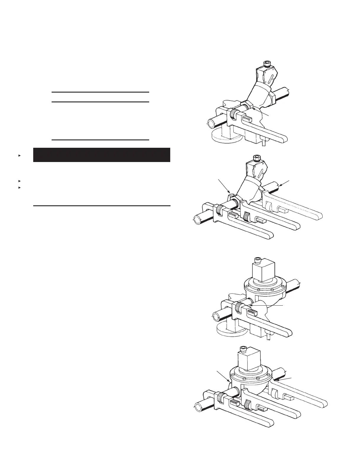
c. Wrench tighten pipe to gas valve. DO NOT USE GAS
VALVE AS A LEVER WHEN INSTALLING OR VALVE
DAMAGE MAY OCCUR. See Figure 5-46.
d. If strainer is utilized, attach strainer ahead of gas valve.
e. If necessary, install drip leg in gas line in accordance
with the authority having jurisdiction.
f. The total length of wire rope allowed for each valve must
not exceed 150 ft (45.7 m).
g. The maximum number of pulley elbows allowed for each
gas valve is 20.
ANSUL MECHANICAL GAS VALVES
000343
CORRECT WAY:
VISE GRIP ENDS NEXT TO PIPE
BEING INSERTED. PREVENTS
EXCESS STRAIN ON VALVE
BODY.
000344
CORRECT WAY:
WRENCH APPLIED NEXT TO PIPE
BEING INSERTED PREVENTS
EXCESS STRAIN ON VALVE BODY.
WRONG WAY:
WRENCH APPLIED
AT THIS POINT
STRAINS VALVE
BODY.
ASCO MECHANICAL GAS VALVES
000345
CORRECT WAY:
VISE GRIP APPLIED NEXT
TO PIPE BEING INSERTED
PREVENTS EXCESS
STRAIN ON VALVE BODY.
CORRECT WAY:
WRENCH APPLIED NEXT
TO PIPE BEING
INSERTED. PREVENTS
EXCESS STRAIN ON
VALVE BODY.
WRONG WAY:
WRENCH APPLIED AT
THIS POINT STRAINS
VALVE BODY.
000346
FIGURE 5-46
 Loading...
