SECTION 5 – INSTALLATION INSTRUCTIONS
UL EX3470 ULC EX3470
PAGE 5-28 REV. 11 2014-SEP-01
R-102 Restaurant Fire Suppression Manual
INSTALLATION OF REMOTE MANUAL PULL STATION OR
MECHANICAL GAS VALVE UTILIZING FLEXIBLE CONDUIT
(Continued)
Connecting the Block and the Faceplate (Continued)
3. Place the faceplate over the top of the electrical box and insert
the two screws to secure the faceplate. See Figure 5-79.
FIGURE 5-79
008012
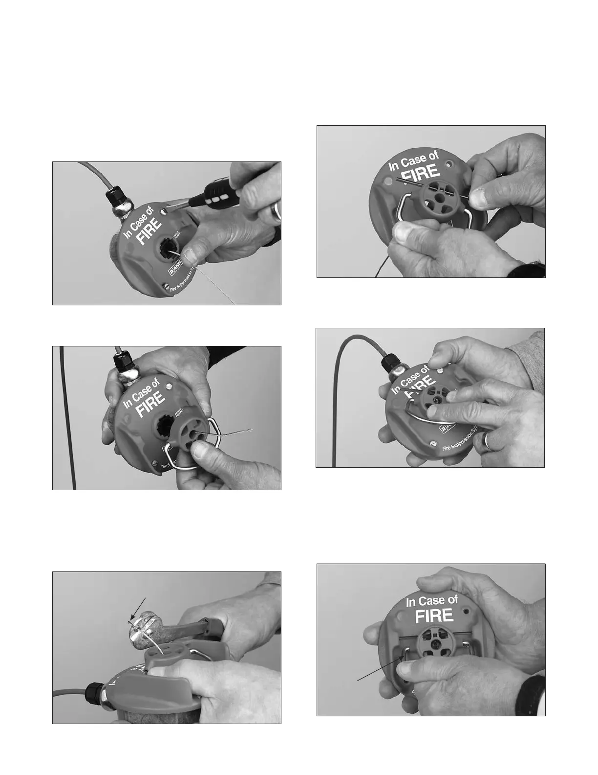
4. Thread the wire rope through the pull knob. See Figure 5-80.
FIGURE 5-80
008013
5. Thread the wire rope through stop sleeve and leave approxi-
mately 1/4-3/8 in. (6.4-9.5 mm) extended past sleeve. Crimp
stop sleeve twice using Crimping tool, National Telephone
Supply Co. Nicopress Sleeve Tool (Stock No. 51-C-887).
Verify stop sleeve is secure on wire rope. See Figure 5-81.
LEAVE 1/4-3/8 IN.
(6-9 mm)
FIGURE 5-81
008014
6. Insert the break rod into the two holes toward the top of the
pull knob. See Figure 5-82.
FIGURE 5-82
008015
7. Pull the excess slack back to the AUTOMAN release. This
will pull the pull knob assembly in place. See Figure 5-83.
FIGURE 5-83
008016
8. Hold the pull knob assembly against the faceplate. Rotate
the pull knob assembly counterclockwise until the break rod
and pull knob snap in place. See Figure 5-84.
Note: Take care in snapping in the ends of the break rod
into the pull station side shields while rotating the entire
assembly.
ROTATE
COUNTER-
CLOCKWISE
FIGURE 5-84
008017
 Loading...
