SECTION 5 – INSTALLATION INSTRUCTIONS
UL EX3470 ULC EX3470
PAGE 5-30 REV. 11 2014-SEP-01
R-102 Restaurant Fire Suppression Manual
INSTALLATION OF REMOTE MANUAL PULL STATION OR
MECHANICAL GAS VALVE UTILIZING FLEXIBLE CONDUIT
(Continued)
Installing Flexible Conduit Through a Conduit Offset
(Continued)
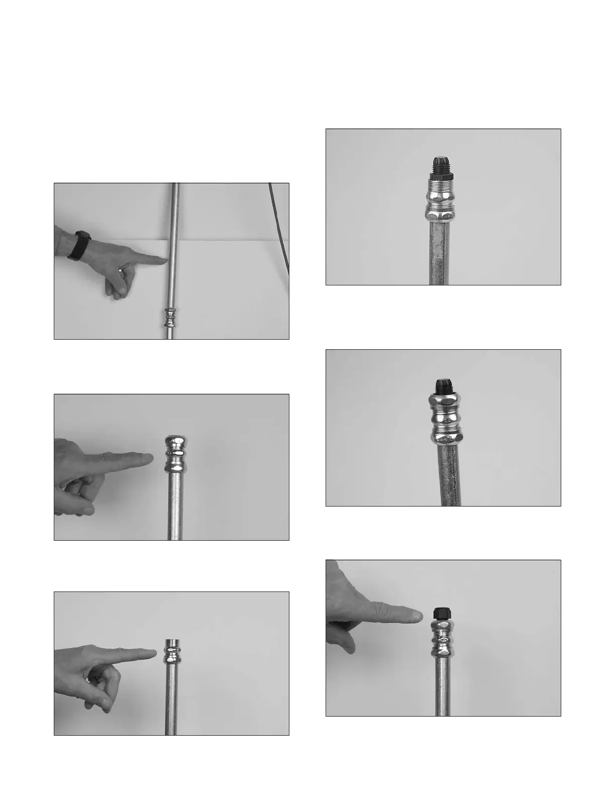
4. Install the conduit required to get above the ceiling. See
Figure 5-89.
FIGURE 5-89
008041
5. Install compression union to top of conduit riser. See Figure
5-90.
FIGURE 5-90
008042
6. Remove union nut and ring. Discard ring. Do not reinstall
nut at this time. See Figure 5-91.
FIGURE 5-91
008043
7. Remove strain relief nut and install strain relief body into
compression union. See Figure 5-92.
FIGURE 5-92
008044
8. Install union nut over strain relief body and tighten nut. See
Figure 5-93.
FIGURE 5-93
008045
9. Install strain relief nut onto strain relief body. Do not tighten
nut at this time. See Figure 5-94.
FIGURE 5-94
008046
 Loading...
