SECTION 8 – MAINTENANCE EXAMINATION
UL EX3470 ULC EX3470
PAGE 8-2 REV. 11 2014-SEP-01
R-102 Restaurant Fire Suppression Manual
SEMI-ANNUAL MAINTENANCE EXAMINATION (Continued)
Alternate Test Method:
The actuation line can also be pressurized with either CO
2
or N
2
from a cartridge or with dry air, CO
2
, or N
2
from a
larger cylinder.
a. Cock the AUTOMAN regulated release assembly and
carefully insert lock bar (Part No. 14985) or lock pin (Part
No. 438031). See Figure 8-9 or Figure 8-10.
b. Make certain expellant gas line hose and/or pipe from
the regulator in the AUTOMAN regulated release is
disconnected from agent storage tanks.
c. Connect Regulator Test Kit (Part No. 56972) to one
of the expellant gas line hoses and securely cap the
remaining hose or pipe. See Figure 8-12.
d. Verify that no cartridges are installed in the AUTOMAN
or the regulated actuator assembly(s).
e. To verify operation of the regulated actuator assem-
bly(s), Pressure Adaptor (Part No. 427560) can be used
to connect to a pressurized CO
2
or N
2
cylinder, instead
of using a CO
2
or N
2
cartridge.
Note: The pressure adaptor assembly comes with a 1/4 in.
NPT pipe plug that is required to be installed in the side of
the adaptor.
f. Install a suitable 1/4 inch air pressure quick connect
fitting (supplied by others) to the bottom of the adaptor.
g. Install and hand tighten the adaptor to the cartridge
receiver and securely attach the corresponding connec-
tor from the gas cylinder hose assembly.
h. With the valve on the regulator test kit closed, remove
the lock bar or lock pin and operate the remote cable
operated pull station to operate the regulated release.
i. Open the pressure cylinder valve to verify that the regu-
lated actuator assembly(s) has operated properly and the
air cylinder has unlatched the ANSUL mechanical gas
valve, if used.
j. Once regulated actuator and gas valve operation is veri-
fied, close the valve on the pressurized cylinder, if used,
and open the valve on the regulator test kit to relieve any
residual pressure.
Note: Although only required at 12 year intervals, the
regulator in the AUTOMAN regulated release can also be
verified. See Maintenance steps on page 8-6.
k. Re-cock the AUTOMAN regulated release and remove
the spent cartridge or pressure adaptor from the cartridge
receiver.
l. If there were leaks in the actuation line or in the 1/8 inch
copper gas tubing for the air cylinder(s), re-tighten the
fittings or replace damaged components.
m. If the cartridge puncture pin in the regulated actuator(s)
did not fully extend, dismantle the actuator and inspect
components of the actuator assembly.
• Oncethepneumaticactuatorisdisassembled,remove
the actuator piston assembly and check the interior
walls of the actuator body for signs of damage or corro-
sion.
• Check the o-ring for elasticity or cuts. Replace, if
necessary. Clean and coat o-ring with a good grade of
extreme temperature silicone grease and reinstall.
• Re-assemble the actuator assembly(s), and reconnect
all actuation and all expellant piping or hose.
6. Remove gasket from cartridge receiver in regulated release
mechanism and each regulated actuator. Check gasket for
elasticity or cuts and replace Gasket (Part No. 181) if neces-
sary. Clean and coat gasket lightly with a good grade of
extreme temperature grease. Reinstall gasket into cartridge
receiver(s).
7. From tank in regulated release assembly: Disconnect the
expellant gas hose from each tank adaptor assembly.
From tank in bracket/enclosure assembly: Disconnect the
expellant gas piping union at each tank adaptor inlet line.
8. Disconnect distribution piping union at each tank adaptor
outlet line.
9. From tank in enclosure: Remove tank. Keep in upright posi-
tion to avoid spilling the agent.
From tank in bracket assembly: Loosen wingnut, disengage
bracket band, and remove each tank. Keep tank in upright
position to avoid spilling the agent.
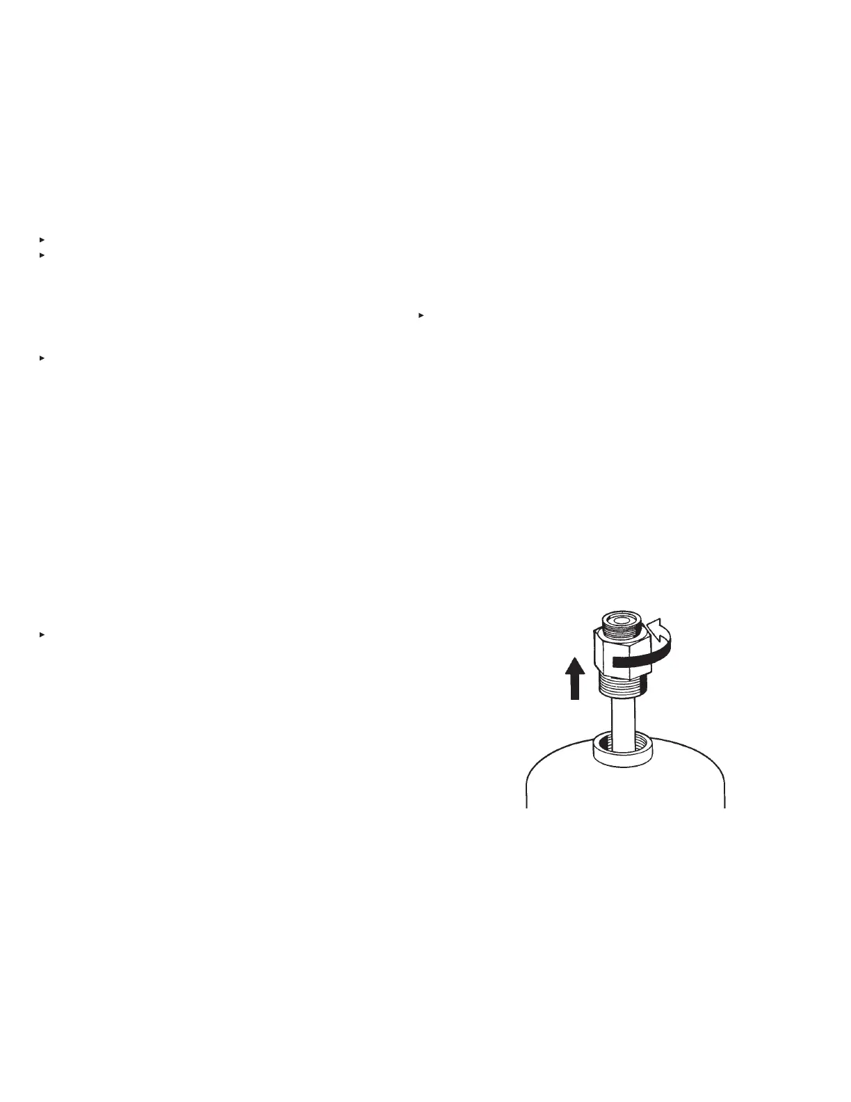
10. Remove tank adaptor/tube assembly from each tank. See
Figure 8-3.
FIGURE 8-3
000291
11. Make certain that each tank is filled with 1.5 (5.8 L) or 3.0
(11.6 L) gallons of only ANSULEX Low pH Liquid Fire
Suppressant. Fill level to be ONLY to the level indicated
in the “Installation” section. See Page 5-3, Figure 5-6, for
detailed filling tolerances.
 Loading...
