SECTION 8 – MAINTENANCE EXAMINATION
UL EX3470 ULC EX3470
PAGE 8-4 REV. 11 2014-SEP-01
R-102 Restaurant Fire Suppression Manual
SEMI-ANNUAL MAINTENANCE EXAMINATION (Continued)
Alternate Test Method: (Continued)
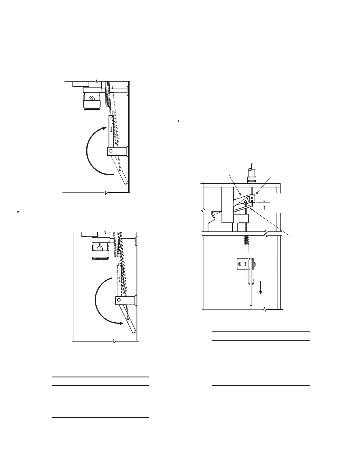
19. Raise tension lever to “UP” position. See Figure 8-6.
TENSION LEVER
IN “UP” POSITION
FIGURE 8-6
000322
20. Install test link (Part No. 24916) in terminal detector.
21. Lower tension lever to “DOWN” position. See Figure 8-7.
TENSION LEVER
IN “DOWN” POSITION
FIGURE 8-7
001096
22. Using wire cutter, cut test link at terminal detector to simu-
late automatic actuation.
NOTICE
If regulated release mechanism does not
actuate, refer to Steps 2 and 3 of “Testing
Detection System” in “Testing and Placing
in Service,” Section 6, Page 6-3.
23. After successful actuation, raise the tension lever to “UP”
position.
24. Remove and destroy all existing fusible links from the termi-
nal and series detector brackets and replace with proper-
ly-rated ANSUL approved, fusible links in accordance with
NFPA 17A.
25. Inspect wire rope at all detector locations, pulley elbows,
pulley tee and at AUTOMAN release. If wire rope shows
signs of wear or fraying, replace entire length.
26. Lower the tension lever to “DOWN” position.
27. Recock the regulated release mechanism and insert the
lock bar or lock pin.
28. Inspect the base of the wire rope locking clamp to make
certain that there is a minimum of 1/4 in. (6.4 mm) and a
maximum of 3/8 in. (9.5 mm) clearance between the base of
the trip hammer locking clamp assembly and the cable lever
assembly. See Figure 8-8.
TRIP HAMMER
ASSEMBLY
CABLE LEVER
ASSEMBLY
LOCKING
CLAMP
1/4 IN. (6.4 mm)
MINIMUM
3/8 IN. (9.5 mm)
MAXIMUM
FIGURE 8-8
000329
NOTICE
If clearance is not between 1/4
in. (6.4 mm) or 3/8 in. (9.5 mm),
raise tension lever to “UP” position,
raise trip hammer 3/8-1/2 in. (9.5-
12.7 mm), tighten set screws, and repeat
Steps 24 and 26.
29. For scissor-style linkage, locate linkage and properly posi-
tion in each bracket all the way toward termination end of
detection run.
30. If a mechanical gas valve is installed, begin the test proce-
dure by removing both side covers.
31. At the regulated release, push the air cylinder rod fully
down.
 Loading...
