SECTION 9 – APPENDIX
UL EX3470 ULC EX3470
2014-SEP-01 REV. 11 PAGE 9-17
R-102 Restaurant Fire Suppression Manual
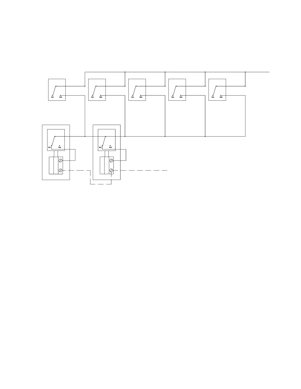
WIRING DIAGRAM (Continued)
Note 1: For fusible link detection only.
Note 2: Use AUTOMAN assemblies with solenoid and electric switch. Replace Single Electric Switch (Part No. 423878) with Dual Switch Kit (Part
No. 423879).
Note 3: See Installation section of this manual for power capacity of solenoid and switches.
Note 4: This method does not provide supervision for battery or system wiring. The authority having jurisdiction (AHJ) may waive this requirement.
Note 5: When any one of the Mechanical AUTOMAN assembies is activated, the microswitch will transfer to the N.O. position, completing the circuit
to the N.C. switch in the Electrical AUTOMAN assemby. This will activate the AUTOMAN assemby. When the AUTOMAN assemby fires, the
N.C. switch transfers to the N.O. position, opening the circuit to the solenoid.
120 VAC
60 HZ
HOT
ACTUATION SOLENOID
NEUTRAL
MECHANICAL
AUTOMAN,
TYP. 5
SWITCH,
PART NO.
423678
ALL SYSTEMS MUST BE CONNECTED TO THE SAME POWER SOURCE
ELECTRIC
AUTOMAN
ELECTRIC
AUTOMAN
#1 #2 #3 #4 #5
FIGURE 4
008406
Simultaneous Actuation of One or More 120 VAC Electric AUTOMAN Assemblies
from Multiple Mechanical AUTOMAN Assemblies
 Loading...
