SECTION 4 – SYSTEM DESIGN
UL EX3470 ULC EX3470
PAGE 4-6 REV. 11 2014-SEP-01
R-102 Restaurant Fire Suppression Manual
Plenum Protection (Continued)
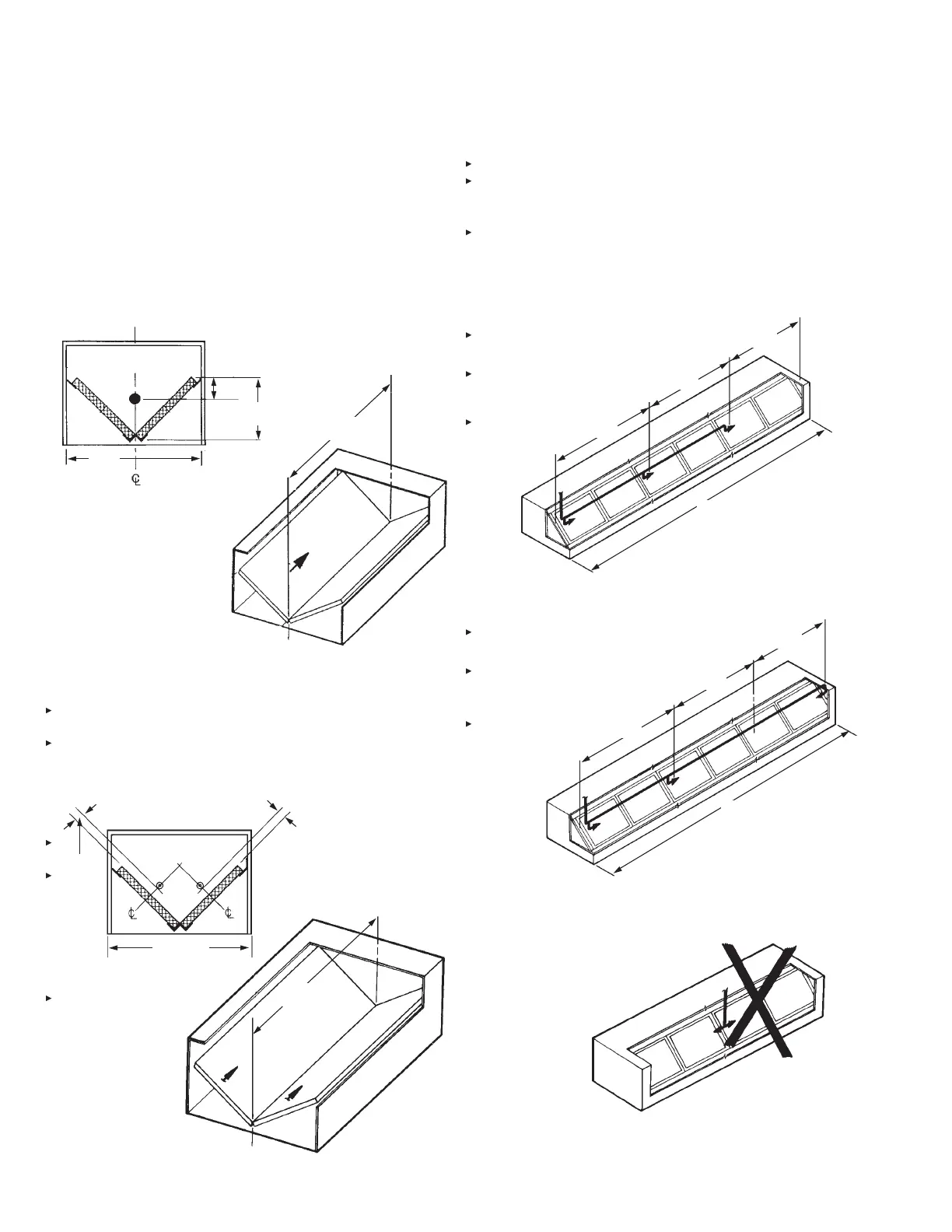
HORIZONTAL PROTECTION – OPTION 2
1W NOZZLE – “V” BANK PROTECTION
One 1W nozzle will protect 6 linear feet (1.8 m) of “V” bank
plenum. The nozzle must be mounted horizontally, positioned 1/3
the lter height down from the top of the lter. Nozzles can be
located at 6 ft (1.8 m) spacings on longer plenums. The nozzle
must be positioned 0-6 in. (0-152 mm) from the end of the hood to
the tip of the nozzle. See Figure 4-10.
FIGURE 4-10
006524
TWO 1N NOZZLES – “V” BANK PROTECTION
Two 1N nozzles will protect 10 linear feet (3.0 m) by 4 ft (1.2 m)
wide of “V” bank plenum. The nozzles must be mounted in the
plenum, 2 to 4 in. (50 to 101 mm) from the face of the lter,
centered between the lter height dimension, and aimed down the
length. The nozzle must be positioned 0-6 in. (0-381 mm) from the
end of the hood to the tip of the nozzle. See Figure 4-11.
FIGURE 4-11
For a plenum, either single or “V” bank, with a linear extension
longer than 10 ft (3.0 m), each bank may be protected using one
1N nozzle every 10 ft (3.0 m) or less depending on the overall
length of the plenum. See Figure 4-12. The nozzles may point
in the opposite directions as long as the entire plenum area is
protected, and the 10 ft (3.0 m) limitation is not exceeded. See
Figure 4-13. The nozzle positioning shown in Figure 4-14 is not
an acceptable method of protection because the plenum area
directly under the tee is not within the discharge pattern of either
nozzle.
FIGURE 4-12
000206
FIGURE 4-13
000207
FIGURE 4-14
000208
6 FT (1.8 m)
MAXIMUM
HEIGHT OF
FILTER (H)
1/3 (H)
1W NOZZLE
4 FT
(1.2 m)
MAXIMUM
000204
10 FT (3.0 m)
MAXIMUM
2 – 4 IN.
(50 – 101
mm)
2 – 4 IN.
(50 – 101 mm)
000203
4 FT (1.2 m)
MAXIMUM
10 FT (3.0 m)
MAXIMUM
10 FT (3.0 m)
MAXIMUM
10 FT (3.0 m)
MAXIMUM
30 FT (9.1 m)
10 FT (3.0 m)
MAXIMUM
10 FT (3.0 m)
MAXIMUM
10 FT (3.0 m)
MAXIMUM
30 FT (9.1 m)
INCORRECT
 Loading...
