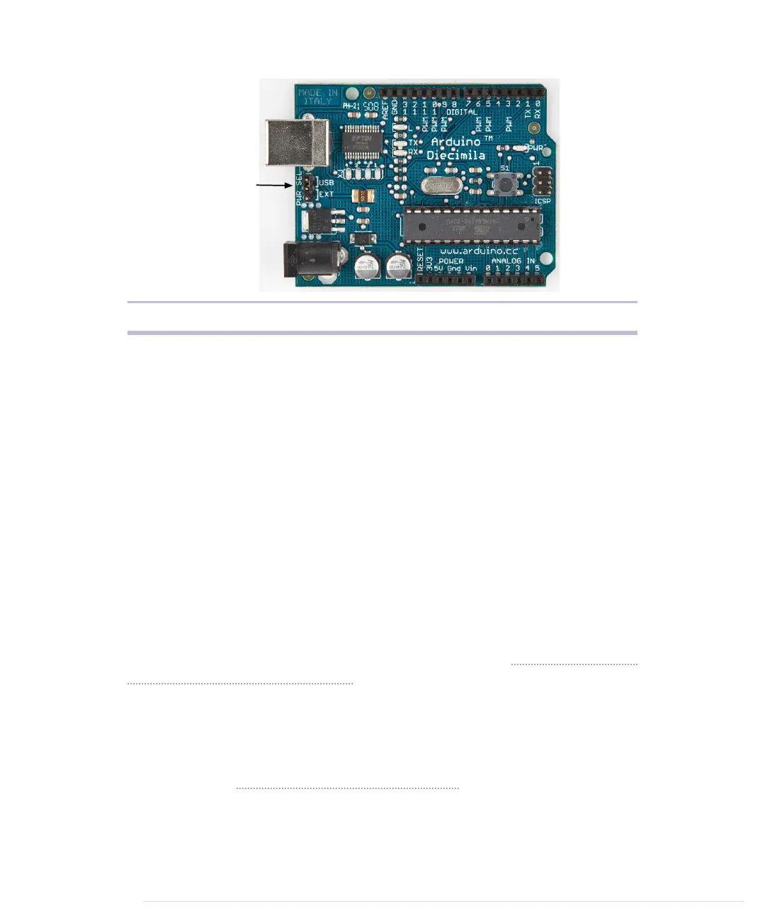
Figure 2—Older Arduinos have a power source selection jumper.
several sockets (sometimes I’ll also call them pins, because internally they
are connected to pins in the microcontroller) related to power supply:
• Using the pins labeled 3V3 and 5V, you can power external devices con-
nected to the Arduino with 3.3 volts or 5 volts.
• Two ground pins labeled GND allow your external devices to share a
common ground with the Arduino.
• Some projects need to be portable, so they’ll use a portable power supply,
such as batteries. You connect an external power source, such as a battery
pack, to the Vin and GND sockets.
If you connect an AC adapter to the Arduino’s power jack, you can access the
adapter’s voltage through the Vin pin.
On the lower right of the board, you see six analog input pins named A0–A5.
You can use them to connect analog sensors to the Arduino. They take sensor
data and convert it into a number between 0 and 1023. In Chapter 5, Sensing
the World Around Us, on page 77, we’ll use them to connect a temperature
sensor to the Arduino.
At the board’s top are 14 digital IO pins named D0–D13. Depending on your
needs, you can use these pins for both digital input and digital output, so
you can read the state of a pushbutton or switch to turn on and off an LED.
(We’ll do this in Working with Buttons, on page 48.) Six of them (D3, D5, D6,
D9, D10, and D11) can also act as analog output pins. In this mode, they
convert values from 0 to 255 into analog voltages.
Chapter 1. Welcome to the Arduino • 8
report erratum • discuss
www.it-ebooks.info

 Loading...