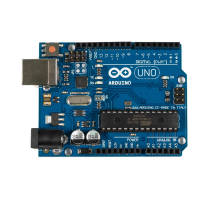
We won’t use the same type of LEDs that are mounted on the Arduino board.
They are surface-mounted devices (SMD) that are difficult to handle. At the
beginning of your electronics career, you will rarely work with SMD parts,
because for most of them you need special equipment and a lot of experience.
They save costs as soon as you start mass production of an electronic device,
but pure hobbyists won’t need them often.
The LEDs we need are through-hole parts. They are named
through-hole parts because they are mounted to a circuit board
through holes. That’s why they usually have one or more long
wires. First you put the wires through holes in a printed circuit
board. Then you usually bend, solder, and cut them to attach the part to the
board. Where available, you can also plug them into sockets as you have them
on the Arduino or on breadboards.
In this section you’ll learn how to work with LEDs on a breadboard. Figure
10, Connecting an LED on a breadboard to the Arduino, on page 43 shows our
circuit. It consists of an Arduino, a breadboard, an LED, three wires, and a
1kΩ resistor. (More on that part in a few minutes.) Connect the Arduino to
the breadboard using two wires. Connect pin 12 with the ninth column of
the breadboard, and connect the ground pin with the tenth column. This
automatically connects all sockets in column 9 to pin 12 and all sockets in
column 10 to the ground. This choice of columns was arbitrary; you could’ve
used other columns instead.
Plug the LED’s negative connector (the shorter one) into column 10 and its
positive connector into column 9. When assembling an electronics project,
parts fall into two categories: those you can mount any way you like and
those that need a special direction. An LED has two connectors: an anode
(positive) and a cathode (negative). It’s easy to mix them up, and my science
teacher taught me the following mnemonic: the cathode is necative. It’s also
easy to remember what the negative connector of an LED is: it is shorter,
minus, less than. If you are a more positive person, then think of the anode
as being bigger, plus, more. You can alternatively identify an LED’s connectors
using its case. On the negative side the case is flat, while it’s round on the
positive side.
When you plug parts or wires into a breadboard, you have to press them
firmly until they slip in. You might need more than one try, especially on new
boards, and it’s often useful to shorten the connectors with a wire cutter
before plugging them into the breadboard. Make sure you can still identify
the negative and positive connectors after you’ve shortened them. Shorten
Chapter 3. Building Binary Dice • 42
report erratum • discuss
www.it-ebooks.info

 Loading...