General Information 5
General Information
cable for the antenna. Total power consumption (including the LNA) is
approximately 2.0 watts for the board and 2.5 watts for the sensor.
Board Hardware
The DG16 Board is simply the DG16 GPS receiver board assembly without the
enclosure, back-up battery, or wide range power supply. It requires a regulated
input voltage of 5 VDC (±5%) or 3.3 VDC (±5%); typical power consumption is
approximately 1.2 to 2.0 watts depending on the configuration. User-entered
parameters can be maintained in the DG16’s internal memory by connecting a 2.5
to 3.5 volt external battery to the appropriate pins on the J301 connector. The
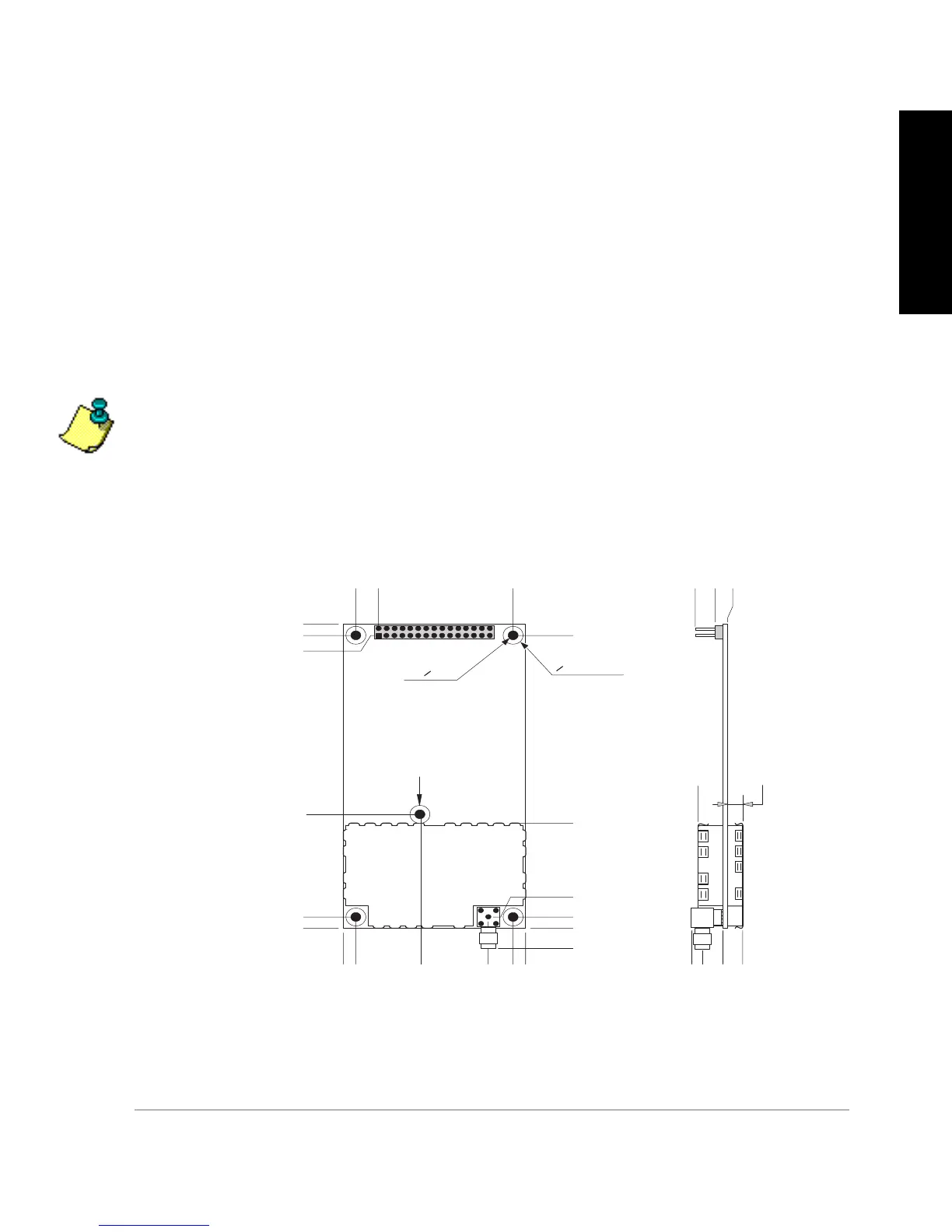
physical dimensions of the DG16 GPS board are shown in Figure 1.1.
The twelve pin connector (J101) on the side of the board is intended for factory use only.
The DG16 uses a standard SMA connector for RF input.
Figure 1.1. DG16 and DG14 GPS Board Dimensions—inches [mm]
0.150[3.81]
0.000[0.00]
0.000[0.00]
0.175[4.45]
1.815[46.10]
2.125[53.98]
2.300[58.42]
0.150[3.81]
0.000[0.00]
1.475[37.47]
4.250[107.95]
4.100[104.14]
4.100[104.14]
4.080[103.63]
0.175[4.45]
2.125[53.98]
0.450[11.43]
0.175[4.45]
-0.285[-7.24]
0.330[8.38]
0.100[2.54]
-0.075[-1.91]
0.375[9.53]
0.250[6.35]
0.000[0.00]
-0.285[-7.24]
0.300[7.62] MAX.
0.200[5.08]
MOUNTING
HOLE 5X
O 0.125
KEEP OUT 5X
O 0.260
0.990[25.15]
1.610[40.89]
NOTE: THE CENTER
MOUNTING HOLE DOES
NOT EXIST ON THE G12