6 DG14 and DG16 Board & Sensor Reference Manual
Sensor Hardware
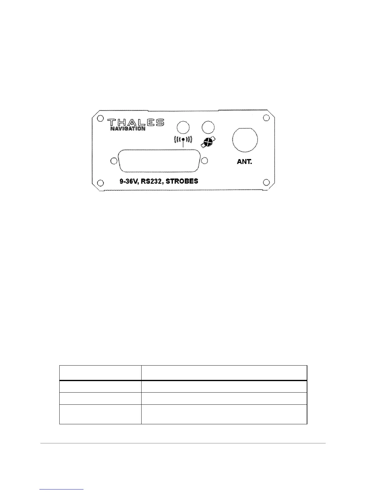
The DG16 Sensor (Figure 1.2) contains the DG16 receiver board a wide range
power supply, and a back-up battery for internal memory in a rugged aluminum
enclosure. It can accept input voltage levels from 9 to 36 VDC, and typical power
consumption is approximately 2.2 watts.
Status LEDs
The DG16 Board and Sensor have two status LEDs: a GPS Status LED and a
Differential Corrections Status LED.
DG16 Board LEDs
The DG16 Board has a three-color LED on the board which indicates the status of
the receiver. Upon power-up the status LED flashes red until a position has been
computed. After computing a position, the status LED flashes yellow or green in
between the red power status flash to indicate the status for each visible
satellite.You can count the number of yellow or green flashes between the red
flash to know the number of satellites visible in the sky. Table 1.3 indicates the
color and status for the LED.
Figure 1.2. DG16 Sensor
Table 1.2. DG16 Board LED Description
LED Color Description
Long Red Flash (0.75 sec) DG16 is computing a position.
Short Red Flash (0.25 sec) DG16 lost the position computation.
Yellow Flash Satellite is locked, but not used in position computation. No
preamble found.