12 DG14 and DG16 Board & Sensor Reference Manual
Interfaces to External Equipment
DG-16 Board Interfaces
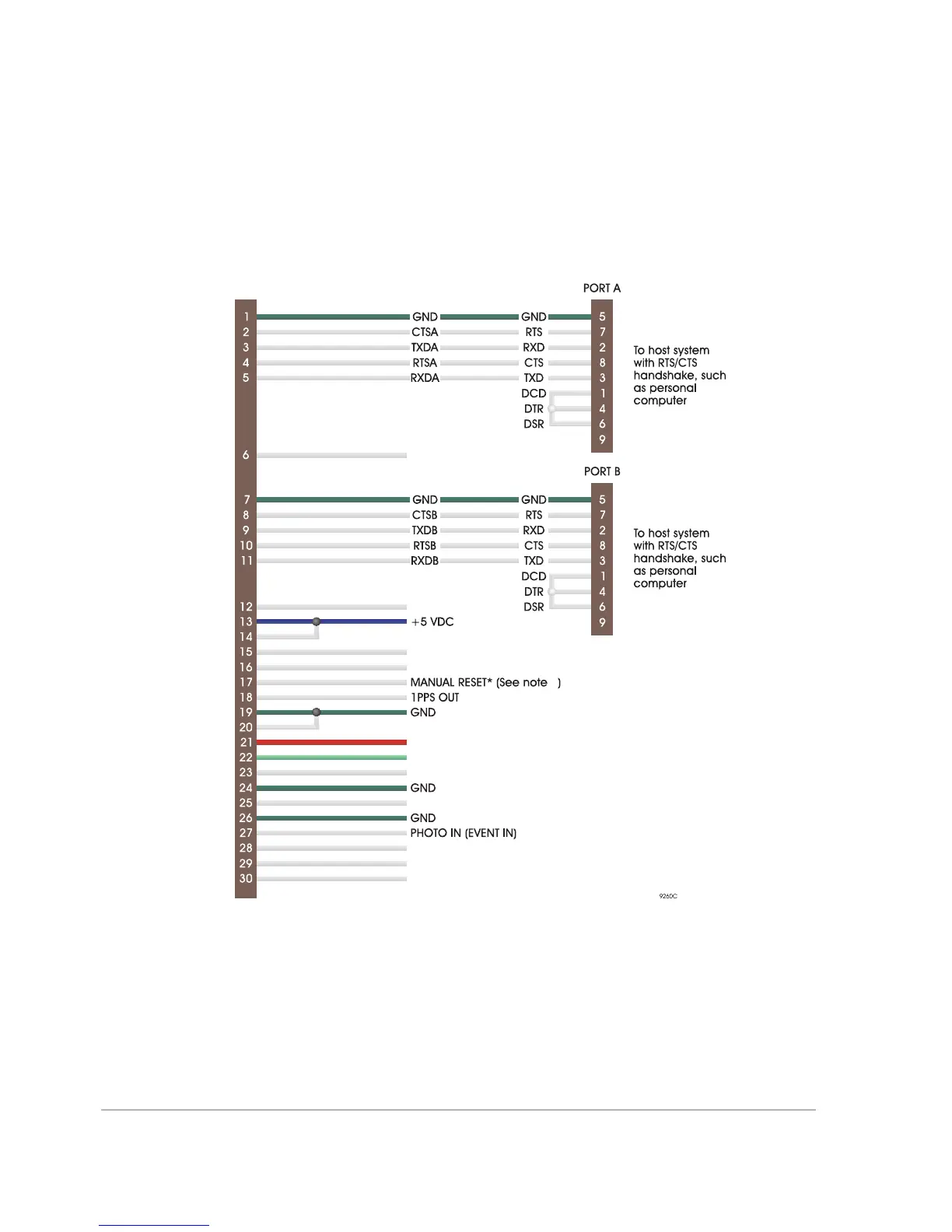
The main interface to the DG16 Board is through the J301 connector. Figure 1.4
shows DG16 interfacing connections for the J301 connector.
Figure 1.4 Note
1. Manual reset (MAN_RES) should be left unconnected if unused. Manual
reset should be activated by a switch or open collector gate.
External LEDs support the same features as the on-board LEDs. See “Status
LEDs” on page 6 for more information.
Figure 1.4. External Equipment Interfacing Diagram
Mates with J301 on D 16G
TXDC
1
TXDSCI
BATT_IN
COR_LED_RED
COR_LED_GRN
EXT_LNA_PWR
RXDSCI
CLKSCI
RXDC
GPS LEN RED
GPS LED GREEN