24 DG14 and DG16 Board & Sensor Reference Manual
Table 2.2 outlines the antenna LNA requirements
Connect the antenna cable directly to the antenna SMA connector on the DG16.
Once power is on and the antenna is connected, the DG16 acquires satellites
(SVs or Space Vehicles) within the field of view of the antenna. As a channel in
the DG16 locks on to a satellite, the LED flashes green or yellow between the red
power flashes for every channel in use (i.e., locked satellites). See “Status LEDs”
on page 6 for a description of the LED flashes.
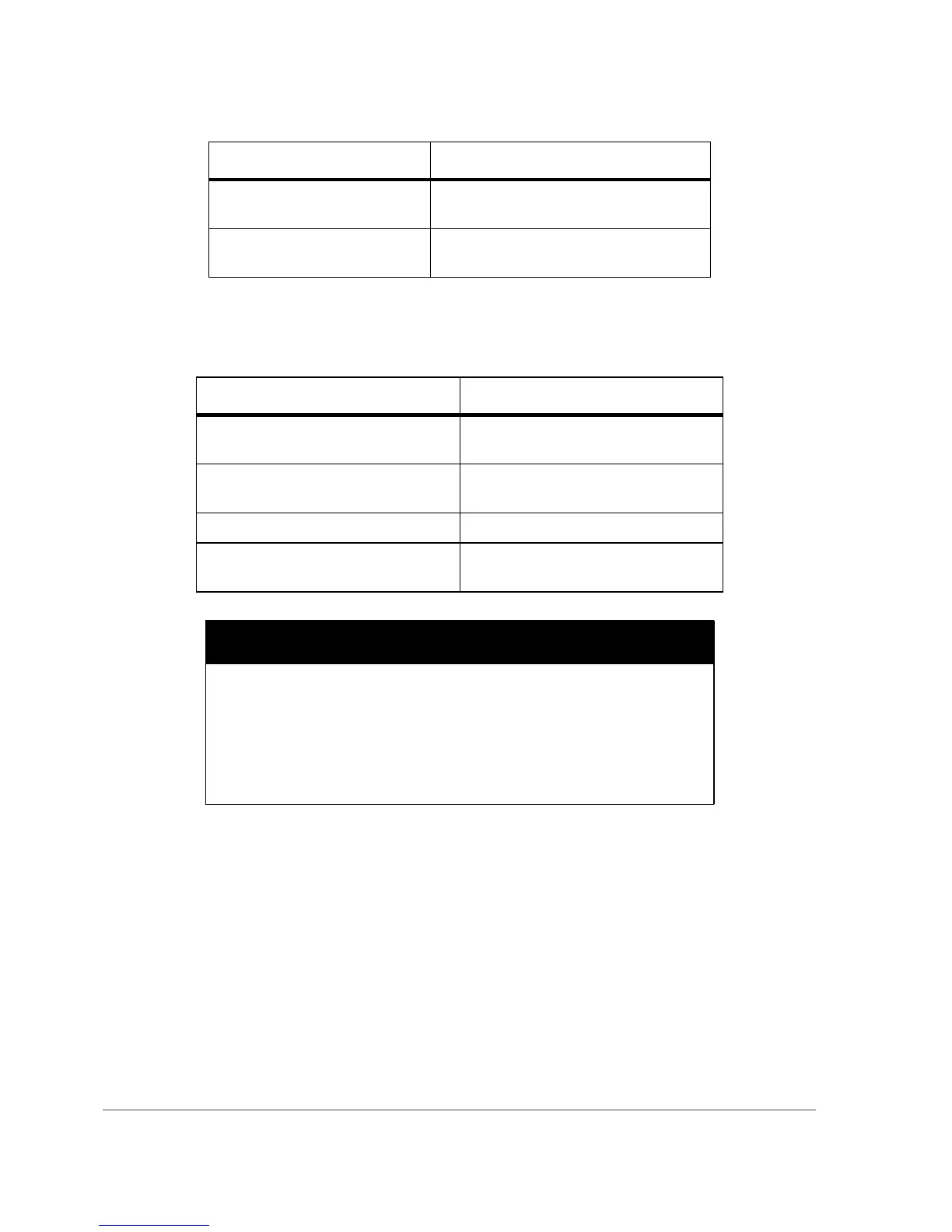
Antenna Gain for Elevation
Angle Greater than 15°
-1 to -2 dB
Antenna Gain for Elevation
Angle of 90°
~ +4 dB
Table 2.2. Antenna LNA Requirements
Requirement Parameter
Impedance of Antenna Output 50 W
VSWR <1.8
LNA Gain Antenna/LNA gain minus the cable
loss: between 20 and 30 dB
Noise Figure < 4.0 dB
LNA Selectivity -3 dB bandwidth: 35 MHz
-20 dB bandwidth: 60-70 MHz
CAUTION
The DG16 may be damaged if the center pin of the RF connector
(Type SMA) is not isolated from DC ground. Provide a DC block
between the center pin and ground; the DC block should have the fol-
lowing characteristics:
• VSWR 1.15 maximum at 1575 MHz
• Insertion loss 0.2 dB maximum
• Maximum voltage 5 VDC
Table 2.1. Antenna Requirements
Requirement Parameter