1
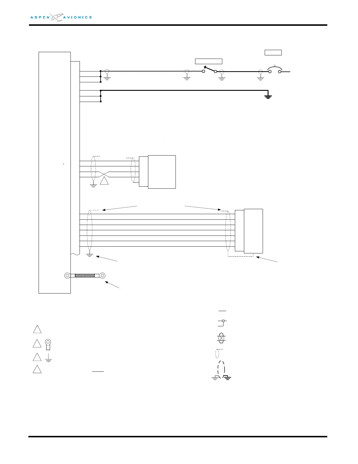
P1
POWER
POWER
2
POWER 3
GND 4
GND 5
GND 6
EFD1000 E5
CONNECTOR
44 PIN F D-SUB
P/N DD44F10000
RSM_A
30
RSM_B
31
RSM_C
32
RSM_D
33
RSM_E
34
RSM_F
35
RSM_G
36
CONFIG_A
CONFIG_B
CONFIG_C
CONFIG_D
1
2
3
4
5
CONFIG_A
CONFIG_B
CONFIG_D
CONFIG_C
CONFIG_S
SINGLE UNSHIELDED
MIL-W-22759
GROUND TERMINAL WIRE
LENGTH 12 INCHES MAX
CONFIGURATION
MODULE
CONNECTOR
Molex P/N 50-57-9045
BREAKER
Wire Types in this Manual
SINGLE SHIELDED 22 AWG
MIL-W-27500
TWISTED SHIELDED PAIR 22 AWG
MIL-W-27500
41
42
44
43
CHASSIS
STUD
1
All wires in this manual are 22 AWG unless otherwise
noted.
2
Connect ground lugs to airframe ground with as short
a conductor as possible.
Connect to airframe ground with as short a conductor
as possible.
3
14-28Vdc
Battery Bus
1
2
3
4
5
6
7
RSM_A
RSM_B
RSM_C
RSM_D
RSM_E
RSM_F
RSM_G
7 CONDUCTOR SHIELDED WIRE
RSM SHIELDING EXTENDS WITHIN
BACK SHELLS
412-00005-001
HIROSE
SR30-10PF-7P(71)
TINNED COPPER OVERBRAID
DABURN P/N 2350-X
CONNECT TO BOLT ON PFD
BRACKET (BACKSIDE OF PANEL) -
AIRFRAME GROUND
GROUND STRAP
8 INCHES
Pigtail Assembly
412-00004-001
20 AWG
20 AWG
24 AWG
24 AWG
22 or 24 AWG X 7 WIRES PFD to RSM
SHIELD TERMINATES TO
“METAL CLAMPER” WITHIN
CONNECTOR
RSM CONNECTOR
4
4
Note wires cross and are not in numerical order
HIRF/ LIGHTNING OVER BRAID OR
DOUBLE SHIELDED WIRE
Black
Brown
Orange
Red
White/Black
White/Red
White/Orange
White/Yellow
White/Green
White/Blue
White
ASPEN EFD
7.5A
EFD