Px001
Px006
46
GNS430/W
GNS530/W
47
24
23
48(50)
49(51)
_
_
_
_
_
_
CNX-80
GNS-480
P5
4
24
5
25
8
28
24
P1001 P1004
23
10
29
48
67
GTN6xx/7xx
_
_
_
_
_
_
25 57
4
Over Braid or
Double Shield
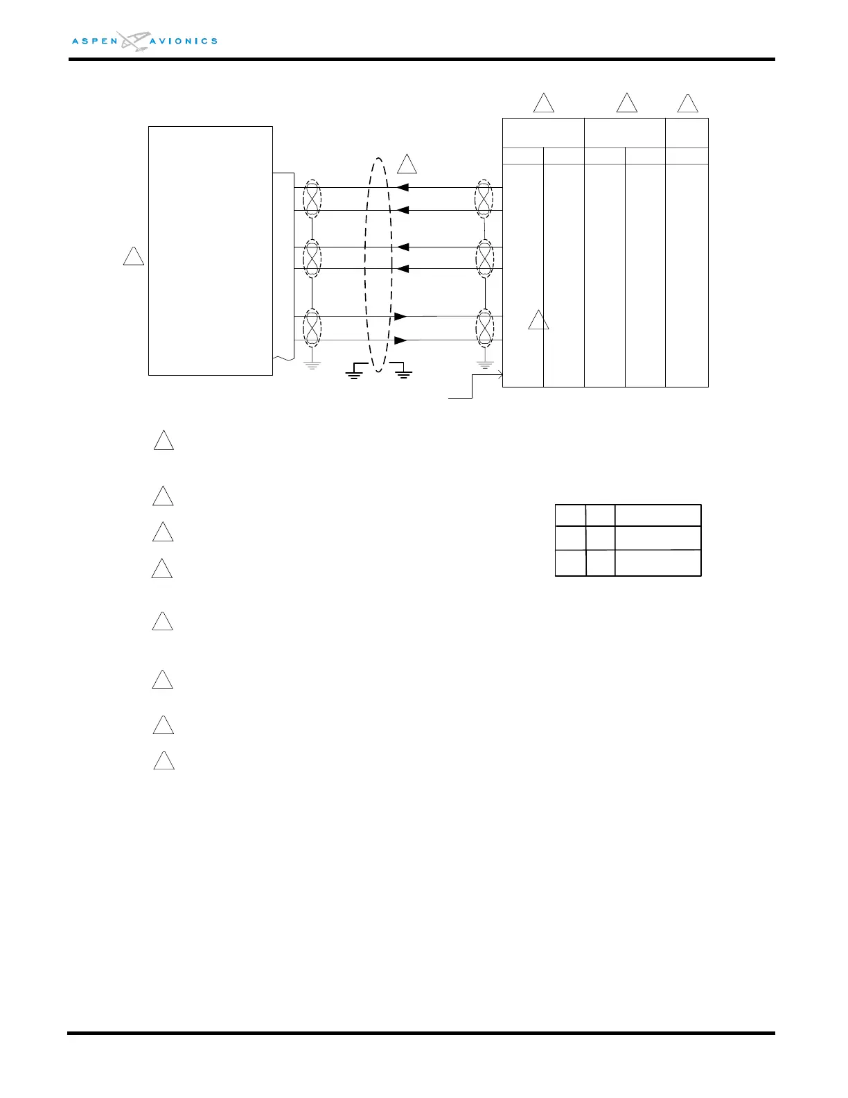
EFD1000
16
429 GPS RX1A
17
18
19
26
27
429 GPS RX1B
429 VLOC RX2A
429 VLOC RX2B
429 GPS/VLOC TXA
429 GPS/VLOC TXB
1
If 429 IN 1 is in use see manufacturers installation
instructions and wire to another unused 429 IN Port.
2
ID#1
Description
A
ID#2
NONE
GNS430, No GPS2
Tracker Autopilot
1
3
2
Use pins 48 & 49 or 50 & 51 not both
GNAV
See Figure 9-27 for GNS/GTN configuration.
*GNS530,GNS480, and GTN650/750 use
same config as GNS430
*GPS500 and GTN625/635/725 uses
same config as GPS400
4
Over shield or over braid required on this wire bundle to
comply with HIRF & Lightning. Extend within back shell.
Ground at both ends.
5
Configuration Matrix
(see Section 10)
5
GPS-400, GPS-500, GTN625/635/725 use same
connections minus the VLOC wiring. PFD pins 18
and 19 are no connect.
C
NONE
GPS400, No GPS2
Tracker Autopilot
6
7
Pins 4 & 24 may be swapped with pins 5 & 25 if configured
accordingly.
7
8
Requires GNS-480 SW v2.3. See Figure 9-27 for GNS-480
configuration.
Refer to manufacturers’ documentation to verify the
integration data and for information regarding checkout
procedures. This drawing, as it pertains to the non-Aspen
equipment, is for reference only.
2
See Fig 9-28A for optional
air data interface