EFD1000 E5 Dual Electronic Flight Instrument (EFI) Install Manual
DOCUMENT # 900-00041-001 PAGE 99-226 REVISION D
© Copyright 2019 Aspen Avionics Inc.
ARINC 429 Port 2 Transmit A
ARINC 429 Port 2 Transmit B
Sin of selected course angle (L)
Cos of selected course angle (L)
OBS sin/cos excitation (L)
Internal +15Vdc reference
ARINC 429 Port 1 Receive B
ARINC 429 Port 1 Transmit B
Active Low signal to drive GPS and Autopilot inputs.
Sin of selected course angle (H)
Cos of selected course angle(H)
OBS sin/cos excitation (H)
26Vac reference to emulate an ARINC synchro
interface
Heading/Course Datum excitation input
Heading/Course Datum excitation offset input
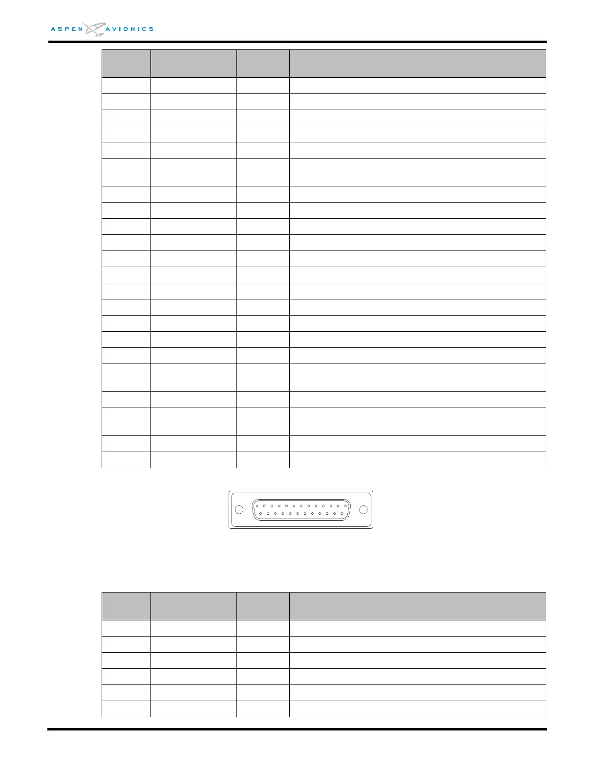
Table 8-15: ACU J3 Pin Out
Figure 8-6: ACU J3 Connector (as viewed from front of unit)
15Vdc power to external equipment
ARINC 429 Port 3 Transmit B
ARINC 429 Port 3 Receive B
400Hz excitation for heading synchro