EFD1000 E5 Dual Electronic Flight Instrument (EFI) Install Manual
DOCUMENT # 900-00041-001 PAGE 204-226 REVISION D
© Copyright 2019 Aspen Avionics Inc.
h) The box TR1or TR2 must be mounted to a metal structure/shelf or bonded to a ground point by
a bonding strap in a location that is accessible for inspection.
i) Shelf or bracket fabrication is beyond the scope of this STC and will require separate FAA
approved data.
j) The box TR1 or TR2 can be mounted in any location of the aircraft that is approved for EA100
mounting.
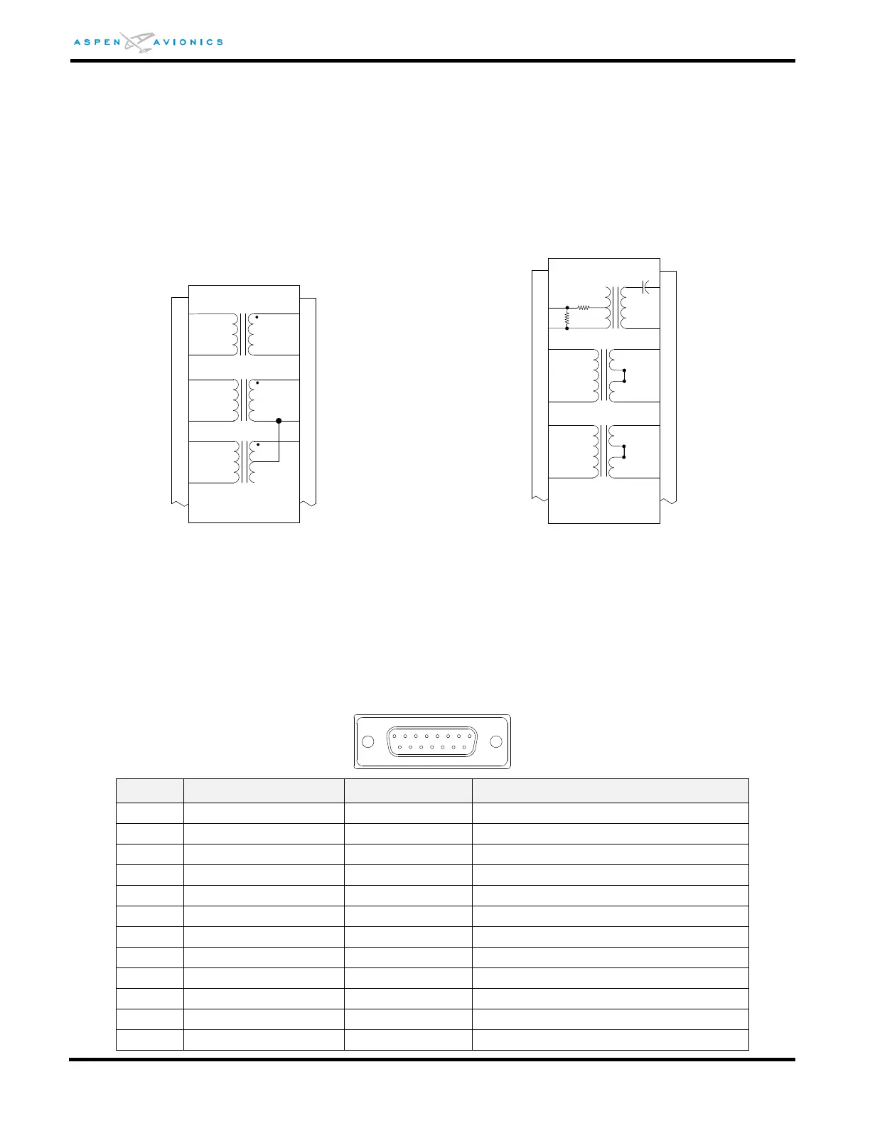
Figure E7: TR1 - Century 21/31/41/2000/4000 Figure E7A: TR2 – Century IIB/III/IV
E5.6 Electrical Connection
EA100 P1 Connector
ETHERNET TX- OUT TO EFD1000
ETHERNET TX+ OUT TO EFD1000
ETHERNET RX- IN FROM EFD1000
ETHERNET RX+ IN FROM EFD1000
5
8
4
3
6
1
P1
7
2
P1
4
5
6
1
2
3
4
5
6
1
2
3
4
5
6
1
2
3
NC
9
10
11
T1 = SP-66
*T2 = SP-66
T3= SP-66
TR1
*T2 not required on C21
5
8
4
3
6
1
P1
7
2
P1
1
3
4
5
6
9
10
11
T1 = SP20
14
*T2 = SP-69
T3 = SP-69
TR2
0.12uF
1.21K
2.2K
4
5
6
1
2
3
4
5
6
1
2
3
* T2 not required on CIIB
jumper
jumper