EFD1000 E5 Dual Electronic Flight Instrument (EFI) Install Manual
DOCUMENT # 900-00041-001 PAGE 86-226 REVISION D
© Copyright 2019 Aspen Avionics Inc.
8 Electrical Connections
8.1 EFD Electrical Specifications
8.1.1 Power Input
Nominal Input: .................. 14Vdc or 28Vdc
Operating Range: .............. 9Vdc to 32Vdc (Note: Input power must transition >11VDC to
turn on the unit)
8.1.2 RS-232 GPS Input
Data is accepted in packets coded in the industry standard "avionics" format at a baud
rate of 9600, 8 data bits, 1 stop bit, no parity. Packets are accepted at approximately 1
Hz.
The following GPS configuration options are available in the Installation menu:
GPS TYPE 1 – KLN94 and KLN90B Standard RS-232 configuration.
GPS TYPE 2 – KLN94 Enhanced configuration. Allows the KLN94 to be configured for
Enhanced RS-232.
GPS TYPE 3 – GX-50/55/60/65 configuration.
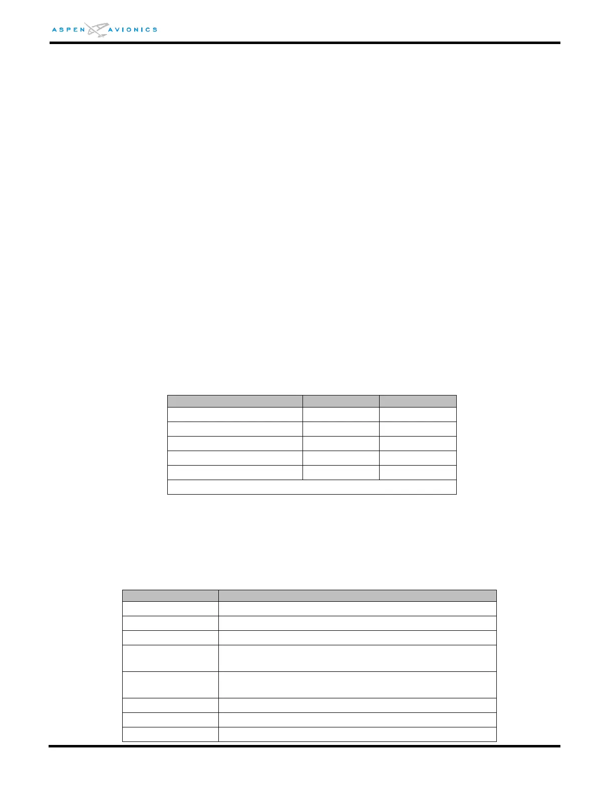
8.1.3 RS-232 ADC Output
The EFD1000 E5 Display outputs the following computed air data output signals over the
RS-232 bus in Format Z (Shadin) (ADC TYPE 1) and Format C (Bendix King) (ADC TYPE 2):
(1) This output is invalid when in “Degraded” mode
Table 8-1: RS-232 ADC Outputs
8.1.4 ARINC 429 GPS Inputs
The EFD receives the following labels on pins (16, 17) and (20, 21) when transmitted
from a GPS receiver. ARINC 429 word definitions are implemented per GAMA Pub 11. The
GPS input ports can be configured either HIGH or LOW.
Label 100, bits 13(0)
and 12(1)
CDI Select (GPS) [GNAV installation only]
Label 100, bits 13(1)
and 12(0)
CDI Select (VLOC) [GNAV installation only]