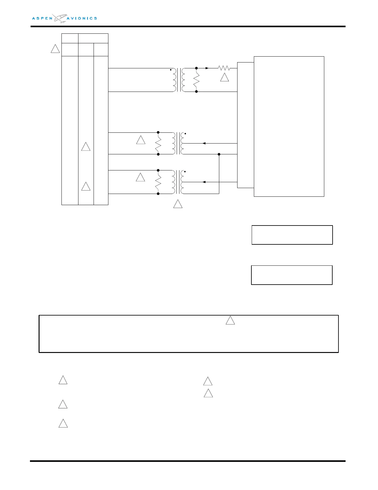
The value of R1 typically ranges from 0K to 50K. A value
for R1 should be selected that sets the NAV intercept angle
at 45 degrees. Consult autopilot manufacturers’ reference
documents for post install checkout procedures.
E
D
A
B
C
1
2
Refer to autopilot manufacturers’ documentation for autopilot-
side integration information (including autopilot STC compliance
data) and for autopilot and flight director checkout procedures.
This drawing, as it pertains to the non-Aspen equipment, is for
reference only.
F
ROLL EXC
ROLL EXC
23
22
3
HDG SIG
CRS SIG
DATUM EXCITATION
HDG DATUM
CRS DATUM
T1
T2
10K :10K
600:600
P3
ACU
(5Khz)
10k
1/4W
1k
1/4W
D
E
A
B
B
T3
ROLL COM
600:600
R1
1k
1/4W
10
SIGNAL COMMON
11
CRS/HDG COM
1
CD33
to DG
1C388-3
CD33
to DG
CD33
to AMP
1C388-2
B
ROLL COM
PARTS:
T1 – Use Triad SP-66 MIL No. TF5S21ZZ.
T2/T3 – New Installations: Use Triad SP-67 MIL No. TF5S21ZZTY.
T2/T3 – Existing Installations: May continue to use a SP-66 unless performance was
unacceptable, then use SP-67.
2
CD33 to DG is the pigtail on the back of the radio coupler.
CD33 to AMP is one of the hard mounted connectors on
the radio coupler.
3
3
3
Pin B is the low side of both T2 and T3. Parallel with any
existing wires on this pin B.
4
T2/T3 Transformer
Some earlier designs of radio couplers have an internal transformer and a lower input impedance. A lower impedance T2 and
T3 (SP-67) may be required to achieve the 45 degree NAV intercept angle. On all new installations it is recommended to use a
SP-67 for T2/T3. Existing installations may continue to use the SP-66 provided system performance is acceptable. A SP-67
may be used provided the 10K parallel resistor is changed to 1k and the value of R1 is adjusted accordingly.
If using the SP-67 use a 1K parallel resistor. If using the SP-66
use a 10K parallel resistor.
4
4
5
4
Set ACU HSI TYPE = 1
Set ACU DATUM = REVERSED
Set ACU HSI TYPE = 3
Set ACU DATUM = REVERSED
1C388-2
1C388-3
_
_
_
_
_
_
4
1
2
3
4
5
6
4
5
6
1
2
3
4
5
6
1
2
3