EasyManua.ls Logo

Aspen Avionics EFD1000 E5 - Rsm Pin out; Configuration Module Pin out; Table 8-11: RSM Pin out; Table 8-12: Configuration Module Pin out

Aspen Avionics EFD1000 E5
226 pages
Print Icon
To Next Page IconTo Next Page
To Previous Page IconTo Previous Page
Loading...
EFD1000 E5 Dual Electronic Flight Instrument (EFI) Install Manual
DOCUMENT # 900-00041-001 PAGE 96-226 REVISION D
© Copyright 2019 Aspen Avionics Inc.
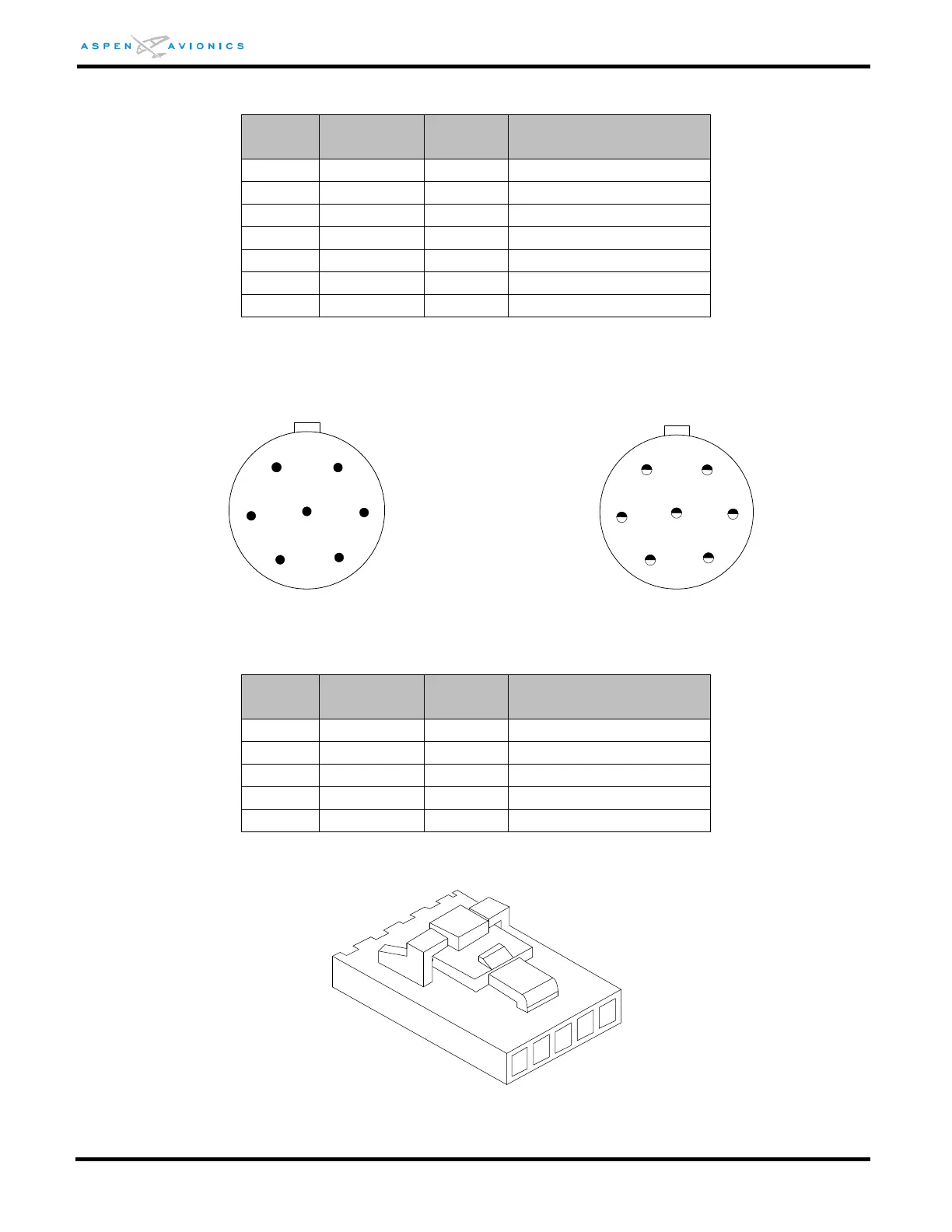
8.5 RSM Pin Out
Pin
Number
Name
Input /
Output
Function
1
RSMA
-
RSM Connection
2
RSMB
-
RSM Connection
3
RSMC
-
RSM Connection
4
RSMD
-
RSM Connection
5
RSME
-
RSM Connection
6
RSMF
-
RSM Connection
7
RSMG
-
RSM Connection
Table 8-11: RSM Pin Out
Male Pin Side Solder Cup Side
Figure 8-2: RSM Mating Connector Install Side
8.6 Configuration Module Pin Out
Pin
Number
Name
Input /
Output
Function
1
ConfigA
-
CM Connection
2
ConfigB
-
CM Connection
3
ConfigD
-
CM Connection
4
ConfigC
-
CM Connection
5
ConfigS
-
Shield Ground
Table 8-12: Configuration Module Pin Out
Figure 8-3: Configuration Module Connector (Install side)
7
6
5
4
3
1
2
7
1
2
3
4
6
5
2
1
3
5
4

Table of Contents

Related product manuals