Over Braid or
Double Shield
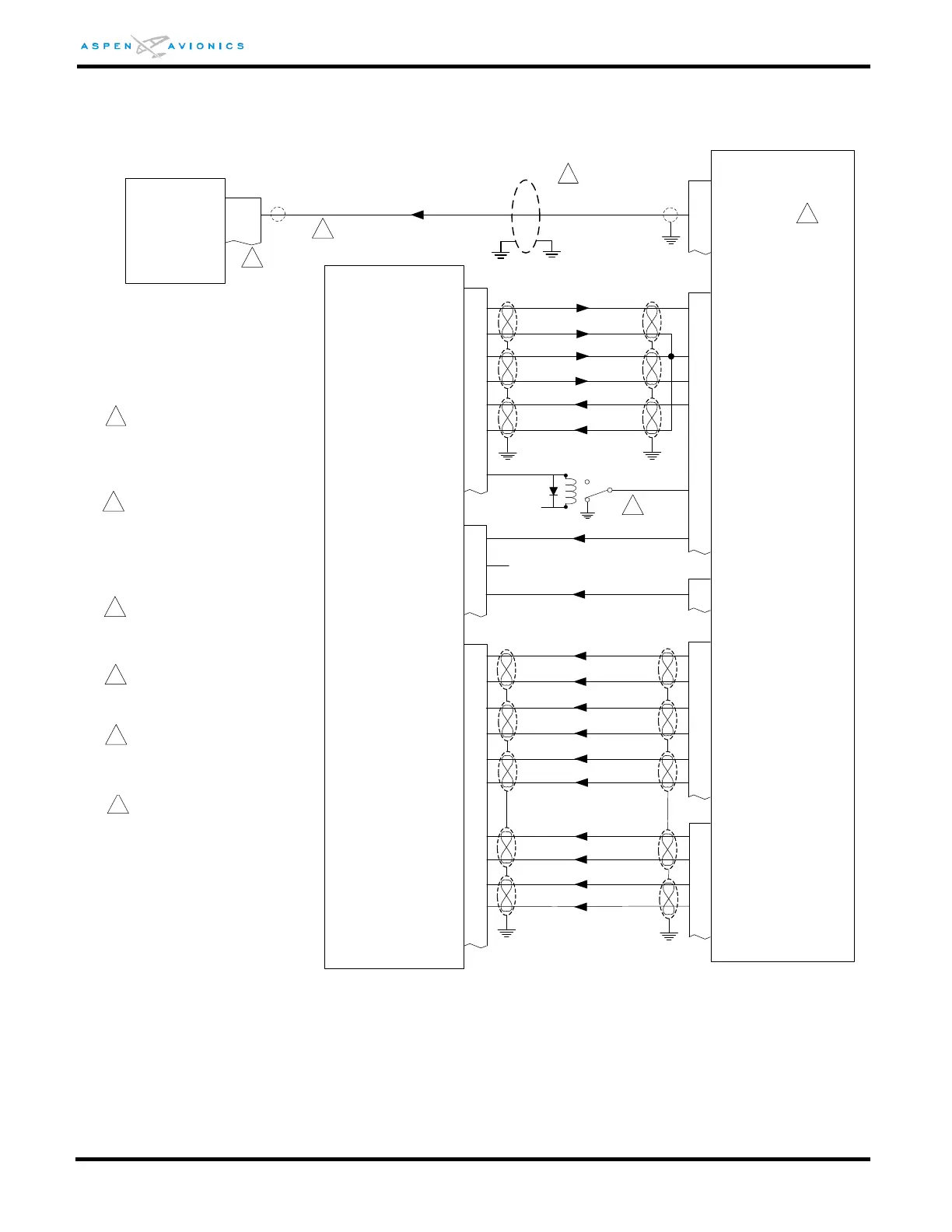
EFD1000
9 (8)
RS232 IN PORT 2 (1)
P3
19
7
ACU
GPS +TO
/FCS-LOC
/OBS-LEG
/APPR ACTIVE
OBS COS +
OBS COS -
1
2
KLN89/B
KLN94
6
18
20
8
36
37
35
34
P2
6
7
24
17
18
P1
4
13
6
12
5
15
11
13
14
12
10
OBS SIN -
OBS SIN +
ROTOR (H)
ROTOR (C)
APPR ACTIVE
FCS LOC /ENG
RS-232 OUT
OBS RESOLVER COS
OBS RESOLVER OUT
AC GROUND
OBS RESOLVER SIN
+TO
+FROM
LAT FLG +
D-BAR +RT
D-BAR +LT
GPS +UP
GPS +RT
GPS +LT
GPS LAT FLG +
GPS LAT FLG -
GPS DISPLAYED
P1
P2
Vert +UP
Vert +DN
12
33
32
P1
31
11
13
8
11
7
14
LAT FLG -
Vert FLG +
Vert FLG -
GPS +DN
GPS Vert FLG +
GPS +FR
GPS Vert FLG -
N/C
P2
P1
17
/GPS MODE SEL
Over shield or over braid
required on this wire bundle to
comply with HIRF & Lightning.
Extend within back shell.
Ground at both ends.
1
2
ACFT PWR
NO
NC
K1
3
2
GPS selected on PFD requires
open to GPS. NAV1 or NAV2
selected on PFD requires
ground to GPS. Use 14V or
28V SPDT relay for K1, P/N
M5757/10.
4
KLN-94 may be configured for
Standard RS-232 or Enhanced
RS-232.
3
Refer to manufacturers’
documentation to verify the
integration data and for
information regarding checkout
procedures. This drawing, as it
pertains to the non-Aspen
equipment, is for reference only.
5
Pin 8 may be used provided the
interface does not include XM
Wx
4
Optionally a twisted pair
(22TG2V64) may be used with
the second conductor grounded
at both ends.
6
5