EFD1000 E5 Dual Electronic Flight Instrument (EFI) Install Manual
DOCUMENT # 900-00041-001 PAGE 71-226 REVISION D
© Copyright 2019 Aspen Avionics Inc.
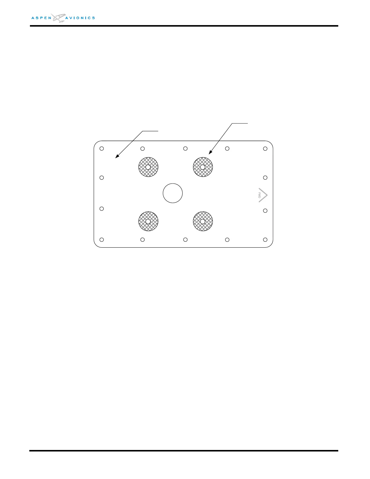
6) Mask around the four (4) mounting holes the diameter of the mounting washers or
1/2" on the down side of the doubler (see Figure 6-22). Prime that side with epoxy
primer per MIL-P-23377. Do not prime the side that faces the aircraft skin. This
allows for a doubler to aircraft skin bond and mounting washer to doubler bond.
7) Mark forward direction on doubler because pattern is not symmetrical.
8) Using the doubler as a template match drill holes in aircraft fuselage at location
determined from Section 6.9.4. Doubler must be aligned to the longitudinal axis of
the aircraft to within ±4º (see Figure 6-14).
Figure 6-20: Masking of Doubler
9) Remove burrs and break sharp edges on the aircraft skin (0.005” – 0.015”)
10) Burnish the aircraft skin on the inner surface in the area where the doubler will
mount. Apply Alodine 1201 and do not prime.
11) The doubler is attached to the inside surface of the aircraft skin with solid rivets.
12) For aircraft skin less than 0.032 thick install with MS20470AD4 protruding head
rivets.
13) For aircraft skin thickness of 0.032 install with NAS1097AD4 rivets flush in the
fuselage skin. Carefully control the countersink depth to not knife-edge the
fuselage skin.
14) For aircraft skin thicknesses 0.040 to 0.050 install with NAS1097AD4 rivets flush in
the fuselage skin.
15) For aircraft skins 0.063 or thicker install with NAS1097AD5 rivets flush in the
fuselage skin.
FWD
Mask four (4) places
Do not primer
Allows for electrical bond
between washer and doubler.
Down side
Primer