EFD1000 E5 Dual Electronic Flight Instrument (EFI) Install Manual
DOCUMENT # 900-00041-001 PAGE 205-226 REVISION D
© Copyright 2019 Aspen Avionics Inc.
Table E4: EA100 P1 Connector Pin Out
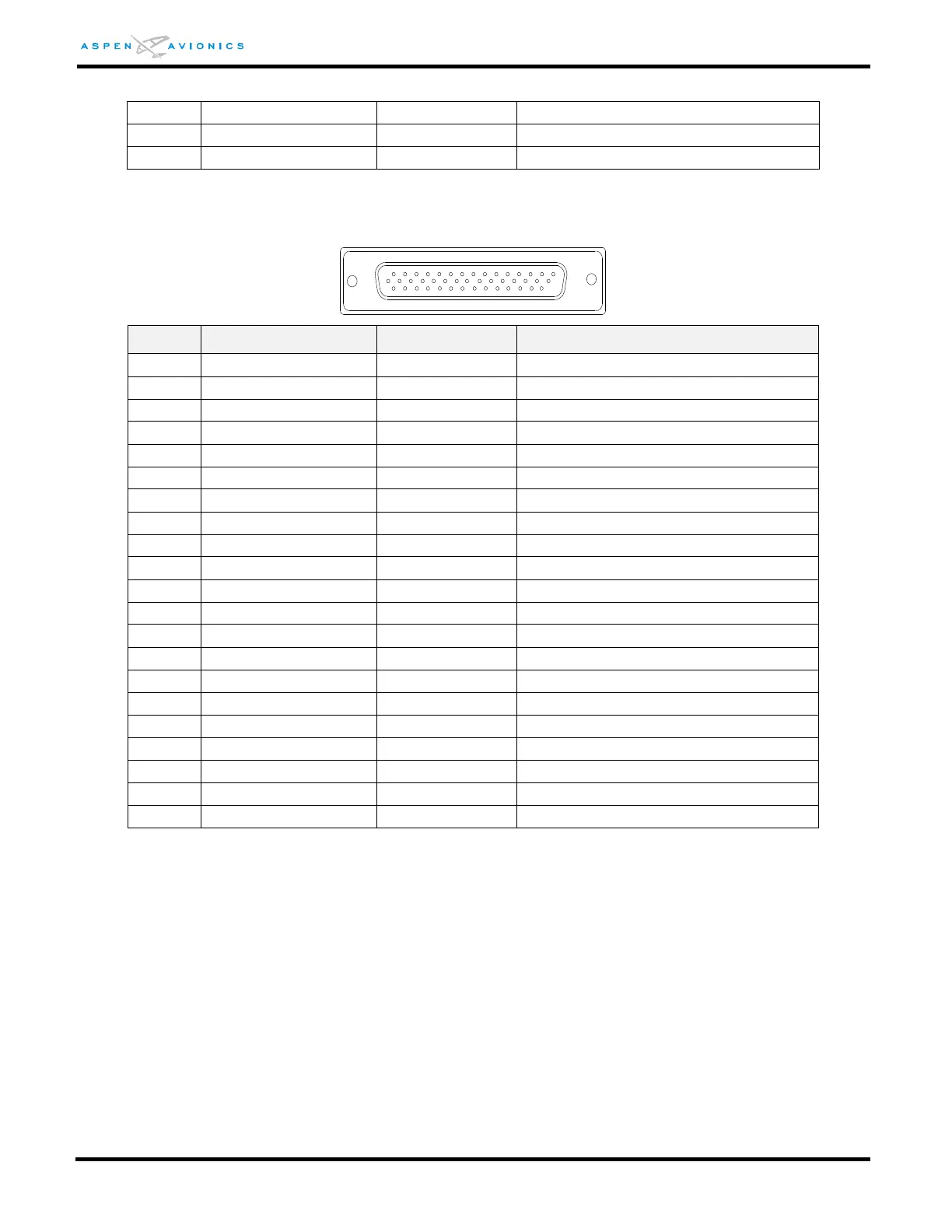
EA100 P2 Connector
ATTITUDE REFERENCE HI (32Vp-p max)
Table E5: EA100 P2 Connector Pin Out
AML STC SA10822SC approves use of the Pitch/Roll attitude outputs for the autopilots identified in this
installation data. Other applications were not evaluated under this STC. Other uses of the TSO EA100
equipment must have separate approval for installation in an aircraft. Refer to the TSO Installation
Instructions (Aspen document 900-00018-001).
E5.7 Wiring Diagrams
A. Wire Figure E8 in all installations.
B. Select Figure E9 – E22 depending on autopilot type and wire as shown.
C. Century autopilots only, build transformer box TR1 or TR2 as shown in Figure E7 or E7A and per
instructions in Section E5.5.