EFD1000 E5 Dual Electronic Flight Instrument (EFI) Install Manual
DOCUMENT # 900-00041-001 PAGE 105-226 REVISION D
© Copyright 2019 Aspen Avionics Inc.
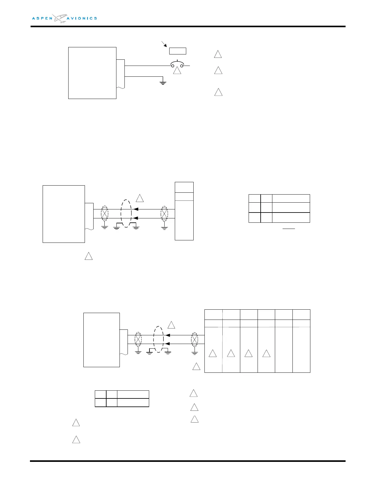
Figure 9-2: ACU/ACU2 Input Power
Figure 9-3: Reserved
Figure 9-4: VFR Only No GPS input configurations
Figure 9-5: ARINC 429 GPS without ACU
ACU #1
10
+14VDC/+28VDC IN
AIRCRAFT GROUND
3
P1
1
All wires are 22 AWG unless otherwise
noted.
2 amp circuit breaker MS26574-2 or
equivalent. Connect to avionics bus or
battery bus if no avionics bus exists.
22
2A
ACU #2
10
+14VDC/+28VDC IN
AIRCRAFT GROUND
3
P1
Optional – ACU #2 is only required
when dual Analog VHF Navigation
receivers are installed.
ACU
LABEL
2
2A
ACU#2
LABEL
3
ACU Chassis must be connected to
airframe ground for proper operation. If
ACU case is not grounded by mounting
to metal shelf or attachment point then a
ground wire from case to airframe
ground must be installed.
ID#1 Description
ID#2
Configuration Matrix
(see Section 10)
NONE NONE
No GPS1, No VLOC1
Over Braid or
Double Shield
EFD1000
18
429 VLOC RX2A
P2002
24
429 VLOC RX2B
19
23
GARMIN
GNC255
1
A429 VLOC
NONEI
No GPS1, VLOC1
1
Over shield or over braid required on this wire bundle to comply with HIRF & Lightning.
Extend within back shell. Ground at both ends.
The only other configuration with no GPS for VFR Aircraft that is
approved is one with an analog NAV – see Figure 9-10
Over Braid or
Double Shield
EFD1000
16
429 GPS RX1A
P4001 P1001 P1
46 10 16
429 GPS RX1B
17
47
29
15
See Figure 9-27 for GPS configuration.
GNS4xx
GNS5xx
GTN6xx
GTN7xx
GNC250/
300/XL
GPS150
155/165
P1
15
16
1
2
1
Apollo
2001
P1
41
40
ID#1 Description
C
ID#2
GPS1, No GPS2
NONE
2
2
2
Over shield or over braid required on this wire
bundle to comply with HIRF & Lightning. Extend
within back shell. Ground at both ends.
3
Configuration Matrix
(see Section 10)
4
Back-up NAV indicator maybe required for IFR
use. Consult manufacturers’ installation manual.
3
Configure GPS for “King EFS 40/50”
5
4
Refer to manufacturers’ documentation to verify
the integration data and for information
regarding checkout procedures. This drawing,
as it pertains to the non-Aspen equipment, is for
reference only.
P901
KLN90
A/B
24
23
GPS