J1-P4
J2-P5
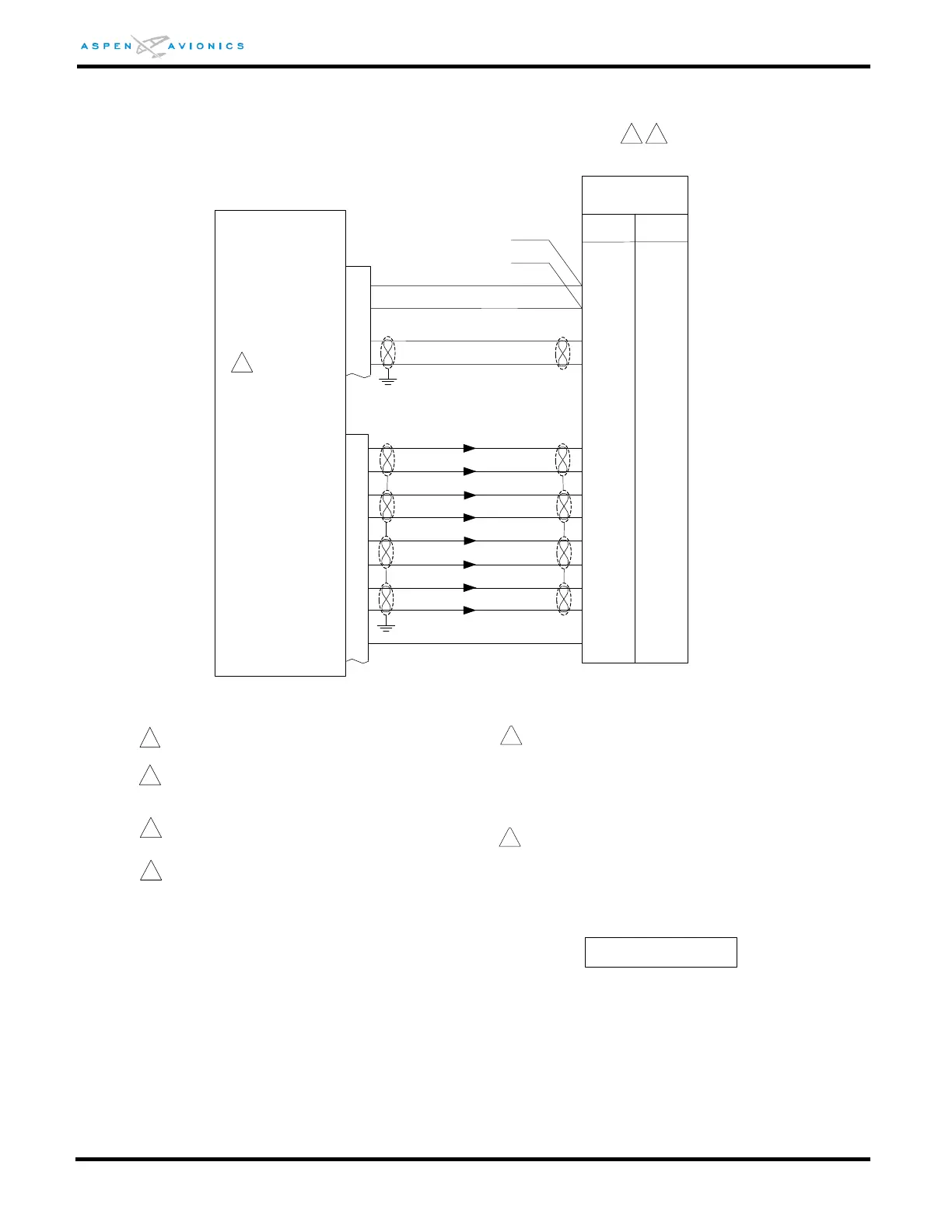
Autopilot can only be connected to ACU #1 in a dual
ACU configuration.
36
17
35
16
30
11
37
18
P2
+ RIGHT
+ LEFT
+ LAT FLG
- LAT FLG
+UP
+DN
+VERT FLG
-VERT FLG
2
_
_
_
_
_
_
_
_
_
_
1
2
This note is not used
5
18
17
_
_
5
9
_
/ILS ENERGIZE
Note – autopilot connections are shown at CA-550A/FD
computer but may route through the S-550A Mode
selector or A/P Accessory Unit. Wire as shown or ACU
may be connected to these units provided NAV1 and
NAV2 inputs are jumpered together.
300B/400B/800B
CA-550A/FD
3
4
Refer to autopilot manufacturers’ documentation
for autopilot-side integration information
(including autopilot STC compliance data) and for
autopilot and flight director checkout procedures.
This drawing, as it pertains to the non-Aspen
equipment, is for reference only.
3
3
CRS DATUM
17
23
22
11
24
21
_
_
P3
HDG DATUM
CRS/HDG COM
HDG-CRS EXT
_
ACU
10
_
2
Existing DG installations must make CRS Datum
connection as shown to gain full HSI features.
Remove Jumper from J2-17 to J1-21 if installed.
CA-550/FD J1-24 and J2-17 may have been
previously connected to ground if they were unused.
These prior connections must be removed.
4
5
6
Set ACU HSI TYPE = 1
Configuration Matrix
(see Section 10)
To other A/P
equipment
(parallel wiring)