Over Braid or
Double Shield
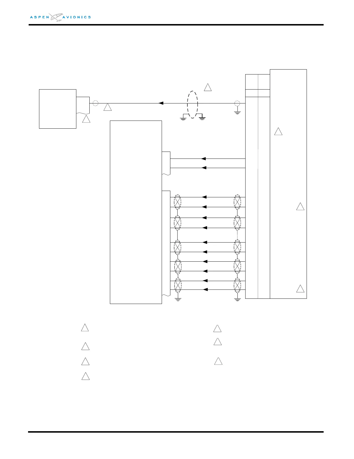
ACU
GPS +TO
1
6
P1
4
12
5
5
11
10
RS-232 OUT
+TO
+FROM
D-BAR +RT
D-BAR +LT
GPS LAT FLG+
GPS +RT
GPS +LT
P1
FLG+
FLG-
4
9
2
11
7
14
GPS LAT FLG-
GPS +FR
2
The GX-50/55/60/65 do not have an OBS
connection.
GPS Vert FLG+
GPS Vert FLG-
GPS +UP
GPS +DN
15
8
13
6
P2
/OBS-LEG
/APPR ACTIVE
7
24
31
30
29
10
14
13
12
11
28
29
Vert FLG+
Vert FLG-
Vert DN+
Vert UP+
34
15
5
_
_
_
_
_
_
P1
GX-55
GX-50
GX-60
GX-65
OBS(HOLD)
ACTIVE
2
3
The GX-50/60 share pin 29 between Vert FLG-
and NAV FLG-.
Configure RS-232 TX Port for “MovMap” in
GPS.
4
GX-50/55/60/65
1
Over shield or over braid required on this wire
bundle to comply with HIRF & Lightning. Extend
within back shell. Ground at both ends.
5
3
3
Refer to manufacturers’ documentation to
verify the integration data and for information
regarding checkout procedures. This drawing,
as it pertains to the non-Aspen equipment, is
for reference only.
Pin 8 may be used provided the interface does
not include XM Wx
6
EFD1000
9 (8)
RS232 IN PORT 2 (1)
4
Optionally a twisted pair (22TG2V64) may be
used with the second conductor grounded at
both ends.
7
6